5.3 Description of Function Codes 5.3.9 d codes (Applied functions 2)
[ 5 ] Position control
Position control can be performed using a feedback signal with PG. Feedback signal pulses are counted at the
inverter, and operation is performed so that the amount of travel is based on the specified position data. Application
is possible under vector control with speed sensor or under V/f control with speed sensor. If performing position
control using a synchronous motor, use an encoder with A-phase, B-phase, Z-phase, and U-phase, V-phase, W-
phase output for the magnetic pole position sensor. With encoders with only an A-phase, B-phase, and Z-phase, it
is not possible to perform position control with a synchronous motor.
An orientation function has also been prepared as a position control response function.
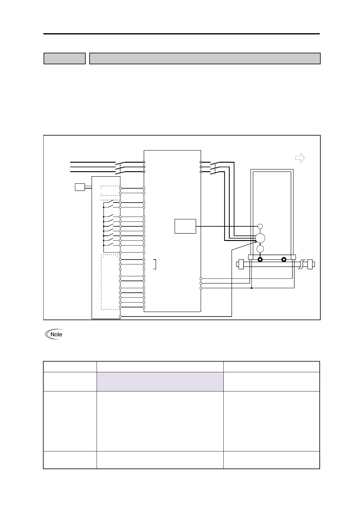
The system configuration is shown in the following diagram.
L1/R
L2/S
L3/T
U
V
W
M
DX+
DX-
RS-485
OPC-PG
PG
OT-(LS) OT+(LS)
30C
30B
30A
X8 (+OT)
X9 (-OT)
CM
FWD
REV
CM
X1 (POS/Hz)
X2 (POS-SET)
X3 (POS-SEL1)
X4 (POS-SEL2)
X5 (POS-SEL3)
X6 (BX)
X7 (TEACH)
CMY
Y1
Y2
Y3
Y4
Y5C
Y5A
FRENIC-MEGA
PG
U
V
W
Do not set direction limit [H08] to 1 or 2 when performing position control. Position control will not function
normally.
The control specifications are shown in the following table.
Vector control with speed sensor: 1:1500
V/f control with speed sensor: 1:200
PG: 1024P/R direct connection
Position control
accuracy
• Motor shaft direct connection:
±1 pulse
• Machine shaft (vector control):
±3 pulses
• Machine shaft (dynamic torque vector control
with speed sensor):
±5 pulses
PG: when 1024P/R used
Control accuracy when multiplying
by 4
Reduction ratio: 1 (excl. gear
backlash)
-99,999,999 to 99,999,999 (user value)
The user value is based on the
electronic gear setting.
Three-phase
AC power supply
Movement direction during
motor forward rotation
RS-485 communication port
Motor
machine brake
operation signal

 Loading...


