PID control
(Dancer reference position
detection width)
Main setting
Remote/Local decision
*1 Priority order when the same function is selected for analog input teminals such as E61 to E63, E66, o60 and o76
U90 > ...>U81 >Terminal [12] > Terminal [C1] >Terminal [V2]>Terminal [V3] >Terminal[32] >Terminal[C2]
Inverter running
"RUN"
Under PID control
"PID-CTL"
Cancel PID control
"Hz/PID"
B
Frequency setting (2)
C
Frequency setting (2)
D
Frequency setting (2)
PID command
PID command for
communication
0
4
1
J02
3
S13
PID control
(Remote Command)
UP/DOWN
control
*1
E61
*1
E62
*1
E63
[12]
[C1]
[V2]
PID Feedback value
3
5
3
5
[12]
[C1]
[V2]
C58
C59
C60
C64
C65
C66
C70
C71
C72
3
5
PID regulator
PID control
(Upper limit value
for PID output)
J18
J19
PID control
(Lower limit value
for PID output)
J58
J03
J04
J05
J59
J60
J61
Reset PID integral and
differential terms "PID-RST"
PID control
(Frequency lower limit value
for PID output)
J10
J59 to J61
within detected
width
×
1
0
MV (Ratio)
MV
(Speed)
J62
Bit: 1 PID control
(Output ratio compensation selection)
Hold PID integral
terms "PID-HLD"
PID control
(Feedbac k filter)
+
-
Alarm
judgement
J13
J12
J11
J105
J106
J107
Display unit
PID control multistage
command "PSS1,2"
PID multistep
command 1
J136
J06
PID multistep
command 2
J137
PID multistep
command 3
J138
J57
PID control (Dancer
reference position)
Dancer
reference position
-10 %
limiter
-110 %
+110 %
-110 %
+110 %
-10 %
limiter
-110 %
+110 %
-10 %
limiter
16 : PID output (MV)
15 : PID command
7 : PID Feedback value
A
Frequency setting (1)
×
0
1
J62
"-1"
Bit: 0 PID control
(PID output
polarity)
LED display
LED display
LED display
23 : PID deviation
LED display
Frequency lower limit value
d152
π
24: Line speed command
LED display
Connection point of
Customizable logic output
SV
PV
Connection point of
customizable logic input
MV
Connection point of
customizable logic input
E
Frequency setting (2)
*1
E66
[V3]
3
5
[V3]
C84
C85
C86
-110 %
+110 %
-10 %
limiter
88888
88888
88888
88888
88888
Frequency
command
Forced operation
judgment
Forced
operation
FMS
Forced operation
(Operation selection)
Forced operation
(Confirmation time)
0.0
0.0
Forced operation
(Set frequency)
Performing forced
operation
FMRUN
Jump
frequency
C01
C02
C03
C04
M05
W02
C94
C95
C96
H118
H116
H117
H118
F15
F16
H63
÷
d41
1.0
1
Application control
selection
×
Cancel PID control
"Hz/PID"
+
+
J01
3
25: Winding diameter
operation value
LED display
Winding
diameter
operation
lnitial winding
diameter D-SET
Wi nding diame ter
oper atio n value
Roll speed
operation
d163
PG pulse
d15
d16
d17
Motor (No. of poles)
Encoder pulse count
Pulse correction coefficient 1
Pulse correctio n coefficient 2
88888
d154
Bit: 0 Constant
surface speed co ntrol
(Selector switch)
P01
Upper/lower
limit warning
judgment
PID control (Dancer u pper limit warning position)
PID control (Dancer lower limit warning position)
d151
d150
Dancer upper limit position warning signal D-UPFL
Dancer lower limit position warning signal D-DNFL
Dancer position limit warning signal D-FL
PID control (Control
selection)
E39
Frequency setting (3)
Addition /
subtraction
processing
d167
0.0
0.0
×
0
1
d153
P
d41
d168
d169
Maximum line speed
Constant surface speed control
(Line speed compensation gain)
Application control
selection
local
remote
Display unit
Maximum scale
Minimum scale
Display unit
Maximum scale
Minimum scale
Display unit
Maximum scale
Minimum scale
Display unit
Maximum scale
Minimum scale
Display unit
Maximum scale
Minimum scale
Display unit
Maximum scale
Minimum scale
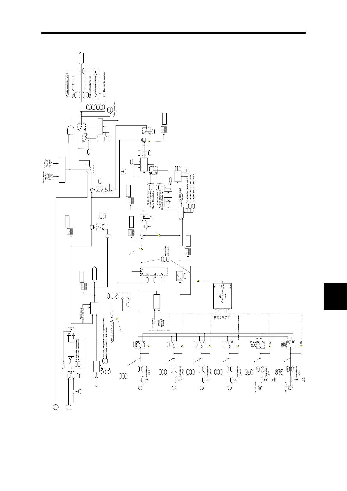
Fig. 8.5-1 PID control section (for dancer) block diagram

 Loading...


