11.9 High Power Factor Power Supply Regeneration PWM Converters (RHC Series)
11-24
11.9 High Power Factor Power Supply Regeneration PWM Converters (RHC
Series)
11.9.1 Overview
■ Compliance with harmonic suppression guidelines
To convert power supply side current to a sine wave with
PWM control in order to significantly reduce harmonic
current, conversion factor Ki in the "Guideline for
Suppressing Harmonics by Customers Receiving High
Voltage or Special High Voltage” issued by the Agency for
Natural Resources and Energy in the Ministry of Economy,
Trade and Industry can be handled as “0” (in other words,
zero harmonics are produced.)
■ Reducing the power supply equipment capacity
Current is supplied with the same phase as the power
supply phase voltage with power factor control, allowing
operation to be performed with a power factor of
approximately 1.
Consequently, the power supply transformer capacity and
devices can be reduced in size over standard type
inverters.
■ Significantly improved braking ability
Regenerative energy when performing high-frequency
acceleration and deceleration operation, or when running
equipment such as elevators is all generated at the power
supply side. This delivers energy-saving benefits when
energy is regenerated.
Furthermore, the current waveform when energy is
regenerated becomes a sine wave, eliminating any
concerns of trouble with the power supply system.
Continuous regeneration rating
1 minute regeneration rating
150% MD (CT)
specification
120% LD (VT)
specification
■ Extensive protection and maintenance functions
(1) Past alarms can be searched using the segment LED.
This allows the cause of alarms to easily analyzed, and
countermeasures to be easily employed.
(2) Gate turn-off is performed when a momentary power
failure occurs, allowing operation to be resumed quickly
once power is restored.
(3) Users can be warned of converter trips beforehand with
early warning signals when overloads or fin overheating
occurs, or when the high power factor power supply
regeneration PWM converter service life is reached.
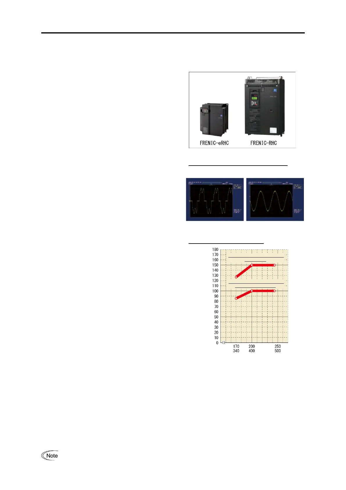
Input current waveform comparison
Permissible characteristics
■ Extensive network support
The FRENIC-RHC series can be connected to MICREX-SX and CC-Link master devices. (Option)
■ FRENIC-RHC, FRENIC-eRHC two series lineup
The FRENIC-RHC series lineup comprises large-capacity models compatible with large-scale systems,
(capacity range 200 V: FRN0146G2S-2G to FRN0432G2S-2G 400 V: FRN0112G2□-4G to FRN1386G2□-4G)
and the FRENIC-eRHC series lineup comprises more compact models than the conventional models.
Fuji Electric also offers a lineup of small-capacity models.
(Capacity range 200 V: FRN0032G2S-2G to FRN0115G2S-2G 400 V: FRN0018G2□-4G to FRN0180G2□-4G)
If an old inverter (FRENIC5000VG7S, FRENIC5000G11S) combined with RHC series is replaced by
FRENIC-MEGA, it might be necessary to make changes to the wiring. Refer to “APPENDIX H” for details.
Allowable regenerative power
Max. allowable regenerative power
(150%, 1min.)
Continuous allowable regenerative
power (100%, continuous)

 Loading...


