+
Pulse
counter
Speed detection
d15
d16
d17
PG pulse
P01/A15/b15/r15
G
G
F14
H13
H14
H09
H49
H16
"STM"
Auto search for
idling motor
speed
Restart mode
after
momentary
power failure
H46
PG
PG interface card
PG pulse
M
3~
88888
88888
LED display
88888
M21
A
Parameter
selector
Calculated torque
88888
88888
M11
M07
d22
d21
d23
M06 M09
M66 M79
Voltage
calculation
DC braking
F21/A10/b10/r10
F20/A09/b09/r09
F22/A11/b11/r11
Motor
constant
H95
DC
braking
start/stop
decision
H95
H195
H80/A41/b41/r41
P01/A15/b15/r15
P02/A16/b16/r16
P03/A17/b17/r17
P06/A20/b20/r20
P07/A21/b21/r21
P08/A22/b21/r21
P16/A30/b30/r30
%R1
%X
P17/A31/b31/r31
P18/A32/b32/r32
P23/A37/b37/r37
P53/A53/b53/r53
P99/A39/b39/r39
F03/A01/b01/r01
F04/A02/b02/r02
F05/A03/b03/r03
F09/A05/b05/r05
F37/A13/b13/r13
F06/A04/b04/r04
F42/A14/b14/r14
A42 b42 r42
I
Main circuit capacitor
Power supply
Rectifying circuit
Cooling fan
ON/OFF control
Detection of
output currents
(Iu, Iv, Iw)
Cooling fan
Motor
Pulse encoder
(Pulse generator)
Current limit level
Instantaneous overcurrent limiting
(Mode selection)
Output currents
(Iu, Iv, Iw)
Comparator
PWM signals
Main power
shutdown detection
Main power
shutdown detection
(Mode selection)
Frequency limiter
(Upper limit)
Position control/
speed control switching
"POS/Hz"
Cooling fan
ON/OFF control
Current limit processing
Alarm code 0C1 to 0C3
LED display
LED display
Torque boost
Load selection /Auto torque boost/Auto energy saving operation
Drive control selection
Maximum output frequency
Base frequency
Rated voltage at base frequency
Maximum output voltage
Disabled when performing auto torque boost
2-phase to 3-phase
transformation
3 : Output voltage
Edc
(DC link
bus voltage)
9 : DC link bus voltage
PWM signals
Carrier frequency
Carrier frequency
reduction processing
Hardware
current limit
Motor sound
(Carrier frequency)
Canceled when
Phase angle
calculation
Inverter overload level
Internal temperature
Heatsink temperature
Starting mode (Auto search)
Starting mode (Auto search delay time 1)
Starting mode (Auto search delay time 2)
Restart mode after momentary power failure
(Mode selection)
(Restart time)
(Frequency fall rate)
(Allowable momentary power failure time)
Speed agreement/PG Error (Hysteresis width)
Speed agreement/PG Error (Detection timer)
PG error processing
Alarm
ere
Auto speed
regulator
(ASR)
Speed control limiter
Parameter
soft-switching
processing
ASR switching time
8: Actual speed/estimated speed
Curren t RMS
value
Detection of
output currents
(Iu, Iv, Iw)
2 : Output current
4 : Output torque
LED display
LED display
Current vibration
damping
No. of poles
Capacity
Rated current
No-load current
Current vibration
damping gain
%X correction factor 1
Magnetic saturation factor 1
Magnetic saturation factor 2
Magnetic saturation factor 3
Magnetic saturation factor c
Motor selection
Lower limiter
(Lower limiting
frequency)
Frequency
limiter
(Lower limit)
(Braking level)
(Braking time)
(Timer at the startup)
DC braking (Response mode)
"DCBRK"
Inverter start
(Response mode)
(Starting frequency)
Select speed control parameter 1
Select speed control parameter 2
Select motor 2
Select motor 3
Select motor 4
"MPRM1"
"MPRM2"
"M2"
M3
M4
Parameter selector 1 to 4
Ready for
jogging
"JOG"
Motor parameter switching
2 to 4
Speed command
Speed Control (Jogging)
(Speed command filter)
Speed control 1 to 4
(Speed command filter)
Speed command filter
Speed detection filter
Speed control 1 to 4
P (Gain)
I (Integral time)
Speed control (Jogging)
P (Gain)
I (Integral time)
Speed control 1 to 4
(Speed detection filter)
Speed control (Jogging)
(Speed detection filter)
Encoder pulse resolution
Pulse scaling factor 1
Pulse scaling factor 2
Motor (No. of poles)
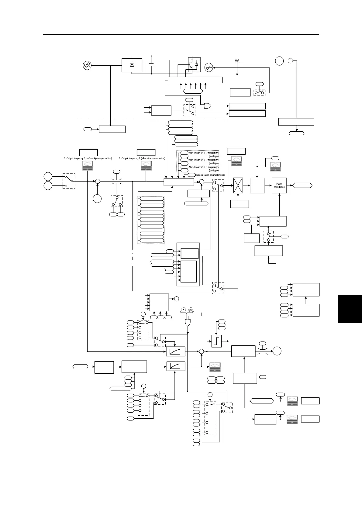
Fig. 8.7-3 V/f control (with speed feedback) section block diagram

 Loading...


