~
~
H64 F16
H64=0.0
F15
H50
H51
+
-
Voltage
calculation
DC braking
F21/A10/b10/r10
F20/A09/b09/r09
F22/A11/b11/r11
Edc
compen-
sation
PWM
calculation
F26
F27
Gate drive circuit
H12
0C1 0C3
H06
1
0
H98
Comparator
H640.0
H71
H95
H52
H53
(bit 0)
F14
H13
H14
H09
H49
H16
STM
H65
H66
H46
H72
DC
braking
start/stop
decision
H95
H195
P12/A26/b26/r26
P10/A24/b24/r24
X
X
X
+
+
Calculated torque
88888
8888888888
88888
88888
M11
M07
M21
M
3~
F03/A01/b01/r01
F04/A02/b02/r02
F05/A03/b03/r03
F09/A05/b05/r05
F37/A13/b13/r13
F06/A04/b04/r04
F42/A14/b14/r14
F42/A14/b14/r14
H68/A40/b40/r40
P09/A23/b23/r23
P11/A25/b25/r25
H80/A41/b41/r41
P01/A15/b15/r15
P02/A16/b16/r16
P03/A17/b17/r17
P06/A20/b20/r20
P07/A21/b21/r21
P08/A22/b21/r21
P16/A30/b30/r30
%R1
%X
P17/A31/b31/r31
P18/A32/b32/r32
P23/A37/b37/r37
P53/A53/b53/r53
P99/A39/b39/r39
d86
F
Main circuit
capacitor
Power supply
Rectifying circuit
Current limit level
Instantaneous overcurrent
limiting (Mode selection)
Output currents
(Iu, Iv, Iw)
Frequency limiter
(Upper limit)
Main power
shutdown detection
Main power
shutdown detection
(Mode selection)
LE D displayLE D display
Acceleration/deceleration
output filter
Lower limiter
(Lower limiting
frequency)
Frequency
limiter
(Lower limit)
Voltage calculation
Current vibration
damping gain
Current
vibration
damping
Deceleration
characteristics
Enable when Auto torque boost is selected.
No. of poles
Capacity
Rated current
No-load current
Magnetic saturation factor c
%X correction factor 1
Magnetic saturation factor 1
Magnetic saturation factor 2
Magnetic saturation factor 3
Motor selection
DC braking
(Response mode)
(Timer at the startup)
"DCBRK"
Inverter start
(Starting frequency)
(Response mode)
Motor constant
Cooling fan
Motor
PWM signals
Cooling fan
ON/OFF control
Current limit processing
Alarm code 0C1 to 0C3
Cooling fan
ON/OFF control
Detection of
output currents
(Iu, Iv, Iw)
LE D display
Torque boost
Load selection /Auto torque boost/Auto energy saving operation
Drive control selection
Maximum output frequency
Base frequency
Rated voltage at base frequency
Maximum output voltage
Disabled when performing auto torque boost
Edc
(DC link
bus voltage)
2-phase to 3-phase
transformation
3 : Output voltage
Phase angle
calculation
Carrier frequency
Motor sound
(Carrier frequency)
(Tone)
Carrier frequency
reduction processing
Hardware
current limit
Canceled when
Inverter overload level
Internal temperature
Heatsink temperature
Auto search for
idling motor speed
Restart mode
after momentary
power failure
Starting mode (Auto search)
Starting mode (Auto search delay time 1)
Starting mode (Auto search delay time 2)
Restart mode after momentary power failure
(Mode selection)
(Restart time)
(Frequency fall rate)
(Allowable momentary power failure time)
LE D display
LE D display
2 : Output current
4 : Output torque
Output current value
Detection of
output currents
(Iu, Iv, Iw)
Current RMS
value
Slip compensation
gain for driving
Rated slip frequency
Slip compensation
gain for braking
Slip compensat ion
Slip compensation
response time
Drive control selection
9 : DC link bus volt age
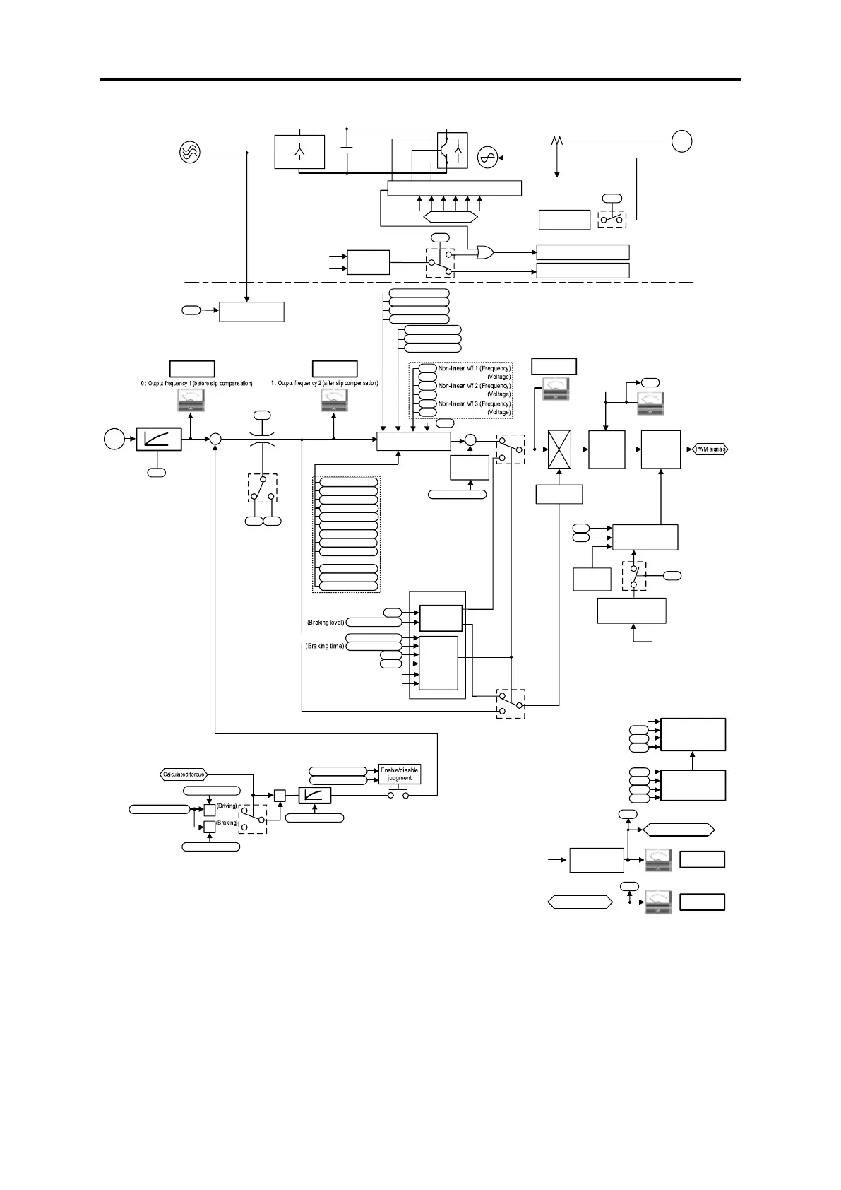
Fig. 8.7-2 V/f control (without speed feedback) section block diagram

 Loading...


