11.9 High Power Factor Power Supply Regeneration PWM Converters (RHC Series)
11-28
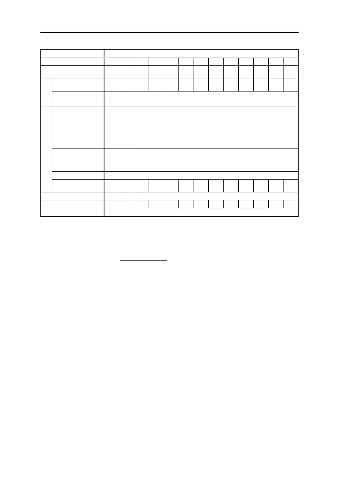
Three-phase 400 V input series (unit type)
Applicable inverter capacity
[kW]
Continuous capacity
[kVA]
Continuous rating of 120 %-1 min
640 to 710 VDC (varies based on input voltage) (*2)
Main power supply
Number of phases,
voltage, frequency
Three-phase three-wire system, 380 to 440 V/50 Hz380 to 460 V/60 Hz (*1)
Control power auxiliary
input
Number of phases,
voltage, frequency
Single-phase 380 to 480 V, 50/60 Hz
Fan power auxiliary
input
Number of phases,
voltage, frequency
Single-phase 380 to 440 V/50 Hz,380 to 480 V/60 Hz
Voltage: +10 to -15% (interphase unbalance ratio: within 2% (*3)), frequency: +5 to -5%
Required power supply
capacity [kVA] (*4)
(Note 1) The specifications are as shown above for function code F03 = 1 (LD (VT) specification).
(*1) The tap inside the converter must be switched when the power supply voltage is 380 to 398 V/50 Hz or 380 to 430 V/60 Hz.
The capacity must be reduced when the power supply voltage is less than 400 V.
(*2) When the power supply voltage is 400 V, the output voltage is approximately 640 VDC, 686 VDC when 440 V, and 710
VDC when 460 V.
(*3) Interphase unbalance ratio (%) =
Max. voltage [V] - Min. voltage [V]
Three-phase average voltage
×67
(*4) Be sure to connect to a power supply with the above required power supply capacity or higher.
(If the power supply capacity is insufficient, the converter or inverter may suffer damage due to waveform distortion at the
power supply side.)
If a power supply boosted with a low-capacity transformer is used for the main circuit power supply, etc. for performing a
control panel sequence check in particular, there is a possibility that problems may occur. In cases such as this, open the
converter “RUN-CM”, and perform a sequence check of other parts without running the converter.

 Loading...


