Alarm 0s
Gate drive circuit
H06
Detection of
output currents
(Iu, Iv, Iw)
Main circuit capacitor
Cooling fan
H72
PM motor
M
3~
Carrier
frequency
PWM
calculation
PWM signals
Vector
Control
LED display
88888
Edc
(DC link
bus voltage)
9 : DC link bus volt age
M21
Alarm code 0C1 to 0C3
P90
F22
F21
P60
P61
P62
P63
P65
P74
P85
P01
P02
P03
Motor 1 (No. of poles)
Motor 1 (Rated capacity)
F26
Current
RMS value
LED display
88888
M11
Detection of
output currents
(Iu, Iv, Iw)
P99
PG
Pulse counter
Speed detection
d15
d16
d17
PG pulse
1 : Output frequency 2
(after slip compensation)
LE D display
88888
P01
Estimated speed
value calculation
F42
= 15
= 16
d32
d33
Torque limit (Speed limit 1)
Torque limit (Speed limit 2)
Speed limit
Step-out
detection
P95
F42
= 16
P30
P87
P89
F42
= 15
d89
d80
Power supply
Rectifying circuit
Output currents
(Iu, Iv, Iw)
Motor 1
(Overcurrent protection level)
Main power
shutdown detection
(Mode selection)
Main power
shutdown detection
2-phase to 3-phase
transformation
3 : Output voltage
PWM signals
Cooling fan
ON/OFF control
Cooling fan
ON/OFF control
PTC or NTC
thermistor
Pulse encoder
(Pulse generator)
Terminal V2
Motor overheat
detection
PG interface card
PG pulse
Voltage RMS
value
Phase angle
calculation
DC braking
start/stop decision
Motor sound
(Carrier frequency)
DC braking (Braking level)
DC braking (Braking time)
DCBRK
2 : Output current
Encoder pulse resolution
Pulse scaling factor 1
Pulse scaling factor 2
Motor (No. of poles)
Drive Control Selection
Alarm
erd
Actual speed
Primary frequency
Motor 1 (reference current at starting)
Motor 1 (flux limitation value)
Motor 1 (Selection)
PM motor high-efficiency control
Motor 1 (pole position detection method)
Motor 1 (Armature resistance)
Motor 1 (d-axis inductance)
Motor 1 (q-axis inductance)
Motor 1 (Iron loss (base speed))
Motor 1 (Rated current)
Motor 1 (NS discriminating current
command value)
Pole position locking frequency
Motor 1 (control switching level)
Motor 1
(pole position sensor offset)
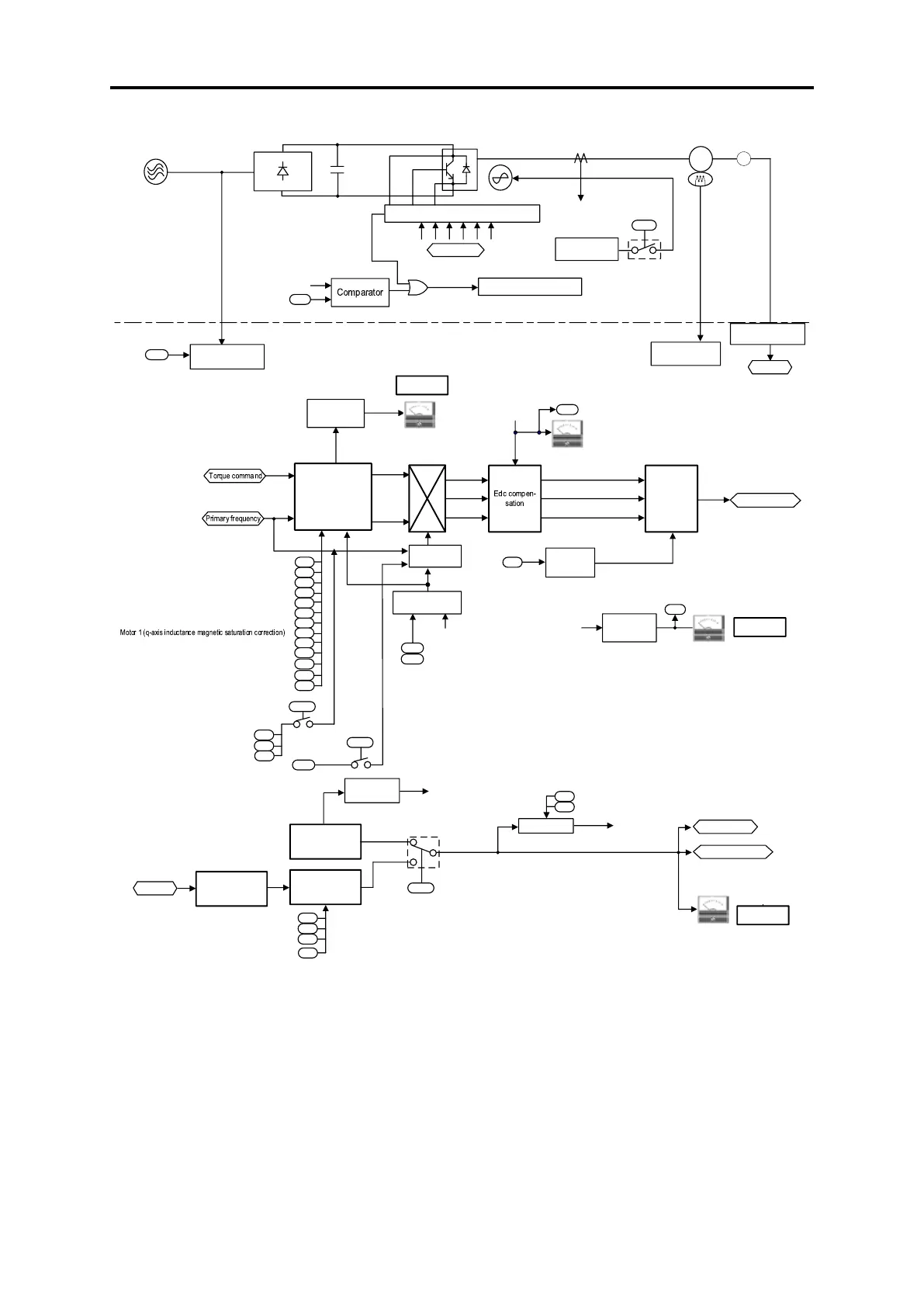
Fig. 8.7-10 Vector control (PMSM drive 2) section block diagram

 Loading...


