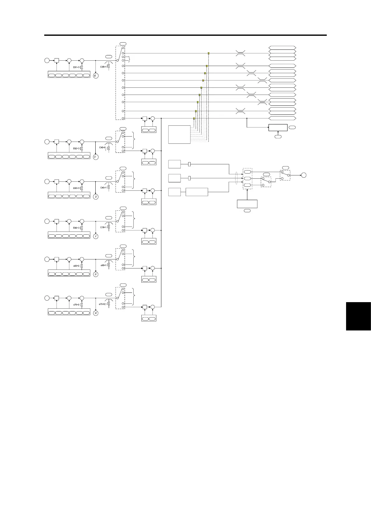
*1 Priority order when the same function is selected for E61 to E63, E66, o60 or o76,
U90 > ...>U81 >Terminal [12] > Terminal [C1] >Terminal [V2]>Terminal [V3] >Terminal [32] >Terminal [C2]
*2 Refer to instruction manual of each option for the details thereof.
Set frequency for
communication
S01
S05
Host
equipment
Host
equipment
Host
equipment
RS-485 communication port 1
RJ-45 connector for connecting keypad
Priority to
later writing
*2
Field bus card
(option)
RS-485 communication port 2
Control circuit terminals [DX+], [DX-]
0
0
F
S01
0
0
S19
S05
Data clear processing
for commu nicatio ns
error
y95
Alarm
er8 erp er4 er5
On occurrence of these errors, it is also possible to clear frequency
command and operation commands (FWD and REV).
0
1,2,15,16
3
5
*3
Terminal [12]
*1
E61
B
6
7,8
9
Terminal [C1]
E62
*1
E63
*1
Terminal [V2]
0
1
20
20
Scale conversion
C59
C60
×
Scale conversion
C65
C66
×
Scale conversion
C71
C72
×
* 100 % = Maximum frequency
Gain
Bias
C32 C34 C55 C56
+
+
×
0
0 limiter
Polarity
selection
0
0 limiter
* PID control block
diagram
* PID control block
diagram
* PID control block
diagram
10,11
0
0 limiter
17,18
17,18
LED display
88888
W33
E42
Display filter
Customizable
logic
U81
・
・
U90
U185
・
・
U188
Bias
C51 C52
+
+
(NB) · S codes show communication related function codes.
Refer to "RS-485 Communication User's Manual" for details.
*3 Refer to the PID control block diagram.
C
Gain
Bias
C37 C39 C61 C62
+
+
×
Bias
C51 C52
+
+
D
Gain
Bias
C42 C44 C67 C68
+
+
×
Bias
C51 C52
+
+
Ratio setting
Auxiliary frequ enc y setting 1
Auxiliary frequ enc y setting 2
Analog torque limiter A
Analog torque limiter B
Analog torque bias
Torque current command
Analog Signal input monitor
・
・
・
Same as
terminal
[12]
・
・
・
C35
Polarity
selection
C40
Polarity
selection
C45
Torque command
Acc./dec.time ratio setting
Analog upper limit frequency
-100 %
+100 %
0 %
+200 %
0 %
+300 %
-200 %
+200 %
-300 %
+300 %
Analog lower limit frequency
0 %
+110 %
0 %
+100 %
0 %
+100 %
12
13,14
Analog speed limit (FWD)
Analog speed limit (REV)
Auxiliary frequ ency setting 3
Auxiliary frequ enc y setting 4
0
1
20
17,18
・
・
・
Same as
terminal
[12]
・
・
・
*1
E66
Terminal [V3]
0
0 limiter
* PID control block
diagram
Scale conversion
C85
C86
×
E
Gain
Bias
C75 C77 C82 C83
+
+
×
Bias
C51 C52
+
+
Polarity
selection
C78
0
1
20
17,18
・
・
・
Same as
terminal
[12]
・
・
・
*1
o60
Terminal [32]
0
0 limiter
* PID control block
diagram
Scale conversion
o70
o71
×
G
Gain
Bias
o62 o64 o66 o67
+
+
×
Polarity
selection
o65
0
1
20
17,18
・
・
・
Same as
terminal
[12]
・
・
・
*1
o76
Terminal [C2]
0
0 limiter
* PID control block
diagram
Scale conversion
o86
o87
×
H
Gain
Bias
o78 o81 o82 o83
+
+
×
Polarity
selection
o75
0
1
20
17,18
・
・
・
Same as
terminal
[12]
・
・
・
+
+
+
+
+
+
+
+
+
+
+
+
Bias
C51 C52
+
+
Bias
C51 C52
+
+
Fig. 8.2-2 Frequency setting section block diagram

 Loading...


