11.3 Molded Case Circuit Breakers (MCCB), Earth Leakage Circuit Breakers (ELCB) and
Magnetic Contactors (MC)
11-7
SELECTING PERIPHERAL EQUIPMENT
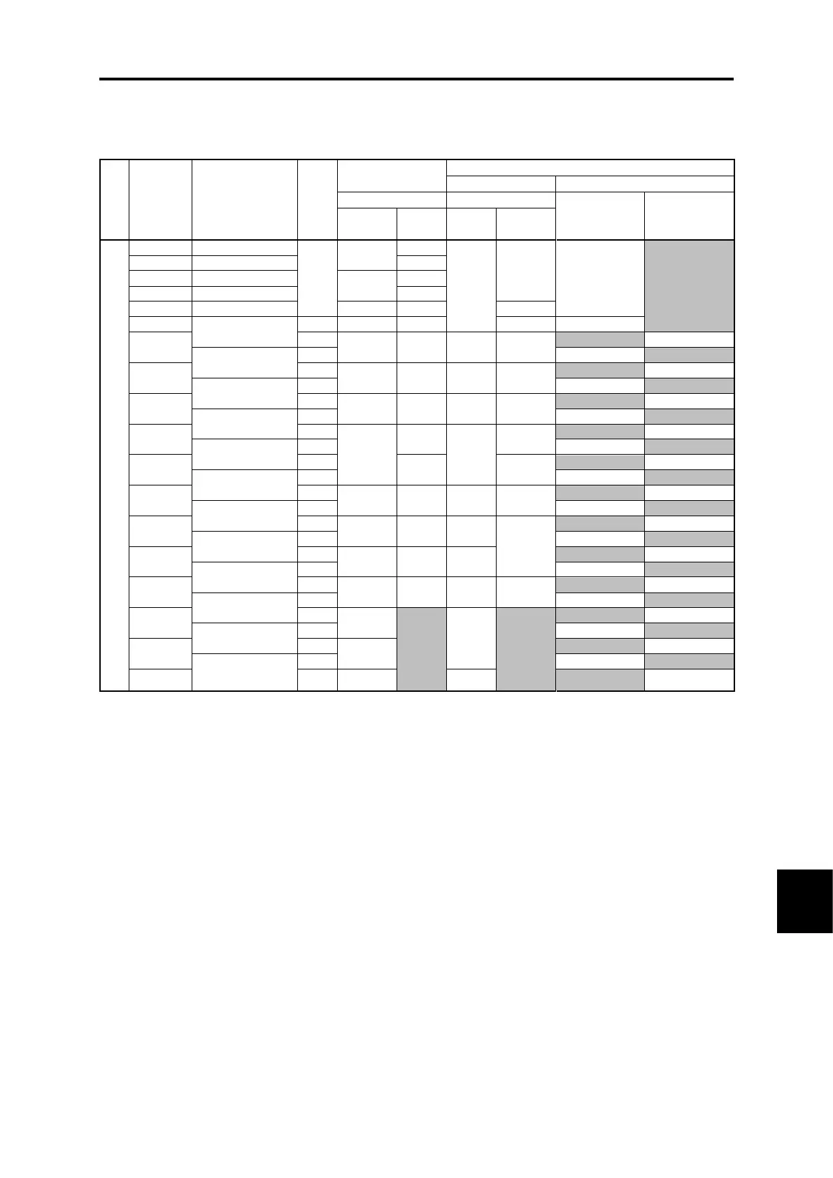
Table 11.3-1 Molded case circuit breaker (MCCB), earth leakage circuit breaker (ELCB), magnetic
contactor (MC)
HHD specification: Heavy Duty applications
HND specification: Normal Duty applications
Standard
applicable
motor (kW)
[HP]
MCCB, ELCB
rated current (A)
(Note)
• Install the MCCB or ELCB at the input side of the inverter. They cannot be installed at the output side of the
inverter.
• The recommended rated current (MCCB and ELCB grounding environment conditions are selected taking the
correction factor (0.85) based on ambient temperature conditions into consideration) under panel internal
temperature of 50 ºC (122 °F) or less is shown for MCCBs and ELCBs. Select an MCCB or ELCB suitable for
the actual short-circuit breaking capacity needed for your power systems.
• HIV wire (tolerant up to 75 ºC (167 °F)) is assumed for the connected wire type when selecting MCs. If selecting
MCs with other wire, it will be necessary to select again taking the terminal block size and wire size into
consideration.
• Use ELCBs with overcurrent protection.
• To protect your power systems from secondary accidents caused by the broken inverter, use an MCCB or ELCB
with the rated current listed in the above table. Do not use a higher rated current than necessary.

 Loading...


