-3-
1.3. NAME AND FUNCTION OF EACH PART
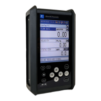
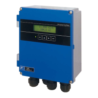
1.3.1. Flow transmitter : FSV···S (IP66)
(9)
(3)
(4)
(5)
(6)
(1)
(8)
(7)
(2)
(10)
(13)
(11)
(12)
(14)
No. Name Key Description
(1) Wiring connection port, large Wiring connection port for power cable and output cable.
(2) Wiring connection port, small Wiring connection port for signal cable only.
(3) Indication and setting unit Indicates and sets the flow rate, etc.
(4)
Received wave diagnostic
indication (LED)
Indicates whether received wave is normal (green) or abnormal
(red).
(5) Escape key
ESC
Returns to the next-higher menu level or cancels the set status.
(6) UP key Selects items, numeric values and symbols.
(7) Shift key Moves the cursor and selects decimal place.
(8) Entry key
ENT
Enters a selection or registers a setting.
(9) LCD display Indicates the flow rate or setting.
(10) Power terminal Connects the power cable.
(11) Input/output terminal Connects signal cable, analog output or DO output cable.
(12) Communication board terminal
Connects communication cable.
(A communication board is optional)
(13) Fuse holder Fuse holder
(14) Communication board Mounted if communication is optionally designated.
 Loading...