-9-
3.3. Flow transmitter wiring
3.3.1. Cautions in wiring
(1) Use a special coaxial cable (FLYC) as a signal cable between the detector and flow transmitter (FSV). Do
not provide a junction or splice of the signal cable midway.
(2) The signal cable between the detector or flow transmitter should be run in metallic conduits. Upstream and
downstream signal cables may be put in the same conduit but, to avoid interference, do not put the power
cable together.
(3) For output signal, use a shielded cable, where possible.
(4) To avoid noise interference, do not put the cables together with heavy duty line or the like into the same
duct.
(5) If a ground wire is included in the power cable, connect it to ground as it is.
(6) A power switch is not provided on the instrument and must be mounted separately.
(7) Seal unused wiring ports by furnished caps.
3.3.2. Applicable wires
Use the following cables.
Power cable : 3-wire or 2-wire cabtyre cable (Allowable temperature: 65°C or more)
Nominal sectional area 0.75mm
2
or more
Outside diameter Ф11mm
Output signal cable : 2-wire or multi-wire cabtyre cable as required (Allowable temperature: 65°C or more)
Outside diameter Ф11mm
Detector-flow transmitter cable : Signal cable by type designation
In case of detector FSSA : High-frequency coaxial double shield cable with
FSSC characteristic impedance of 50Ω
FSSD With one-side waterproof BNC connector
FSSH Outside diameter Ф7.3mm
In case of detector FSSE High-frequency coaxial double shield cable with
characteristic impedance of 50Ω
Outside diameter Ф7.3mm
3.3.3. Treatment of wiring port
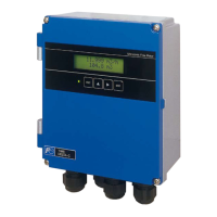
The casing of the flow transmitter is IP66 and IP67. However, if installed in a humid place, the wiring ports must be made
airtight to avoid ingress of moisture, condensation, etc. Be sure to use the waterproof glands furnished with the instrument
in order to ensure the waterproof means. A gland, which is not ready to be used, should be sealed by supplied cover.
Do not install the instrument where there is a risk of flooding.
CAUTION
CAUTION
 Loading...