-11-
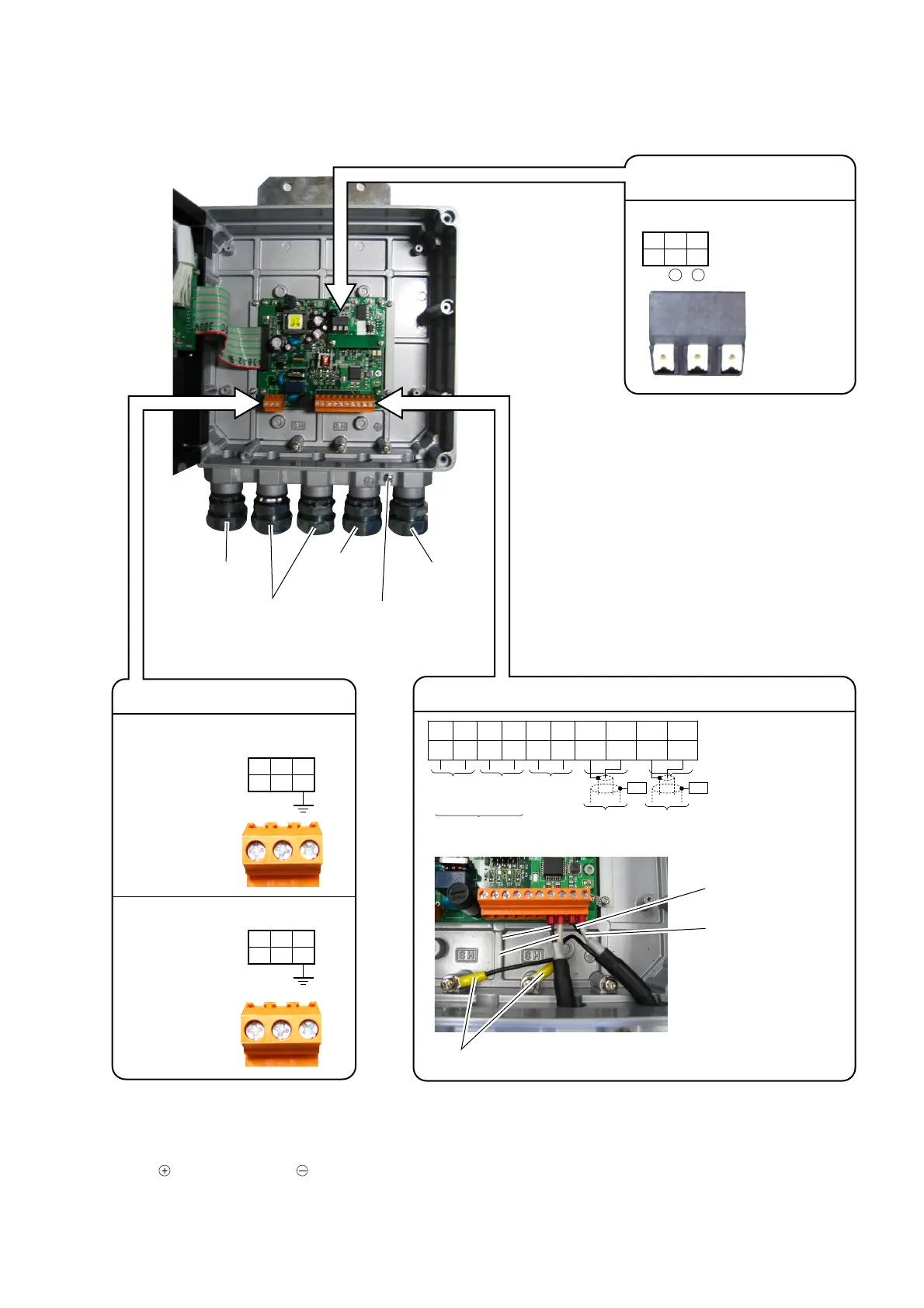
3.3.4.2. Flow transmitter : FSV···H (IP67)
Carry out wiring to each terminal according to the following figure.
SG A
-
B
+
123
RS-485
L N FG
123
+
-
FG
123
+
--
+
DO1 DO2
+
-
I out
GND
HF1 HF2
GND
123456 7 8 910
TO SENSOR
SHSH
DOWN STRUP STR
TROUT
DC30V, 50mA
-
+
White
Black
Yellow
Iout : Analog output
DO1, 2 : Transistor/open
collector
To downstream
sensor
To upstream
sensor
Black
White
Main board terminal block
Power supply board terminal block
AC power supply
100 to 120V AC
or 200 to 240V AC
50/60Hz
DC power supply
20 to 30V DC
Power cable
Downstream
sensor cable
Output signal cable
(analog output, DO1,
DO2, Communication)
Upstream
sensor cable
External
ground terminal
(M4)
Communication board terminal
block (option)
Note 1) Terminal block is insertion type to connect a cable. Use bar terminal as crimp-style terminals.
Note 2) Be sure to connect ground terminal to external ground terminal. (Class D grounding)
Note 3) For output signal, use multiple core cable as required.
Note 4) Differential signal line of RS-485 consists of two pins.
means B+, and means A-.
 Loading...