Chapter 3 Component Status
3.6 Controller Enclosure Detail
ETERNUS Web GUI User’s Guide (Operation)
Copyright 2016 FUJITSU LIMITED P2X0-1260-19ENZ0
125
● For the ETERNUS DX500 S3/DX600 S3, the ETERNUS DX8700 S3/DX8900 S3, and the ETERNUS AF650
The following items are displayed in the Main area:
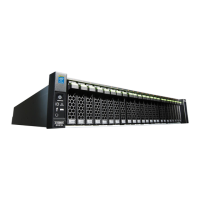
- Storage system image
The rear view of the CE that is installed in the ETERNUS DX/AF is displayed.
The CM status, the CA status, and the Controller enclosure Power Supply Unit (CPSU) status are
displayed with icons.
By clicking the CM number, the [Controller Module] screen is displayed. Refer to "3.7 Controller Module
Detail" (page 127) for display items.
By clicking the CA number, the [Channel Adapter] screen is displayed. Refer to "3.8 Channel Adapter
Detail" (page 132) for display items.
By clicking the CPSU number, the [Controller Enclosure Power Supply Unit] screen is displayed. Refer to
"3.10 PSU/CPSU (CE) Detail" (page 140)
for display items.
- Parts
The CM number, the CA number, and the CPSU number is displayed.
By clicking the CM number, the [Controller Module] screen is displayed. Refer to "3.7 Controller Module
Detail" (page 127) for display items.
By clicking the CA number, the [Channel Adapter] screen is displayed. Refer to "3.8 Channel Adapter
Detail" (page 132) for display items.
By clicking the CPSU number, the [Controller Enclosure Power Supply Unit] screen is displayed. Refer to
"3.10 PSU/CPSU (CE) Detail" (page 140)
for display items.
- Status
The status of each component is displayed. Refer to "A.5 Component Status" (page 410)
for details.
 Loading...