CHAPTER 3
Small Configuration
Installing the 19-Inch (FC9682HSW3) Heat Baffle
3-51
FLASHWAVE 7500 Release 6.1
Equipment Installation
Fujitsu and Fujitsu Customer Use Only
FNC-7500-0061-200
Issue 1, May 2009
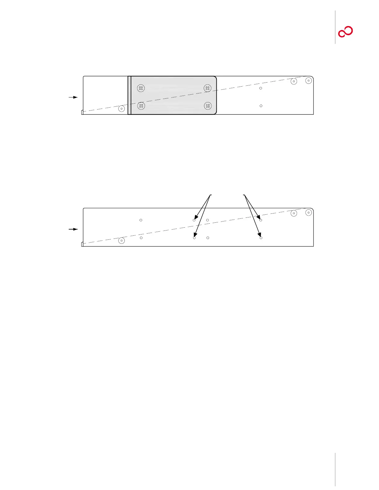
Figure 3-35 [p. 3-51] shows a right-side view of the heat baffle after the flange is mounted.
7 Proceed to Step 10 [p. 3-52].
8 Identify the flange mounting holes for 23-Inch rack installation on the side of the heat baffle.
See Figure 3-36 [p. 3-51].
9 Using four pan-head Phillips M4 screws (8 mm long) on each side, secure the left and right
shelf flanges to the heat baffle as shown in Figure 3-32 [p. 3-49].
Figure 3-35: Flange Mounted on Right Side of Heat Baffle (19-Inch Rack Installation)
Figure 3-36: Flange Mounting Holes on Right Side of Heat Baffle (23-Inch Rack Installation)
Front
Mounting Holes
m1656ti_1