CHAPTER 3
Small Configuration
Installing the LAS2 Shelf
FNC-7500-0061-200
Issue 1, May 2009
FLASHWAVE 7500 Release 6.1
Equipment Installation
3-66
Fujitsu and Fujitsu Customer Use Only
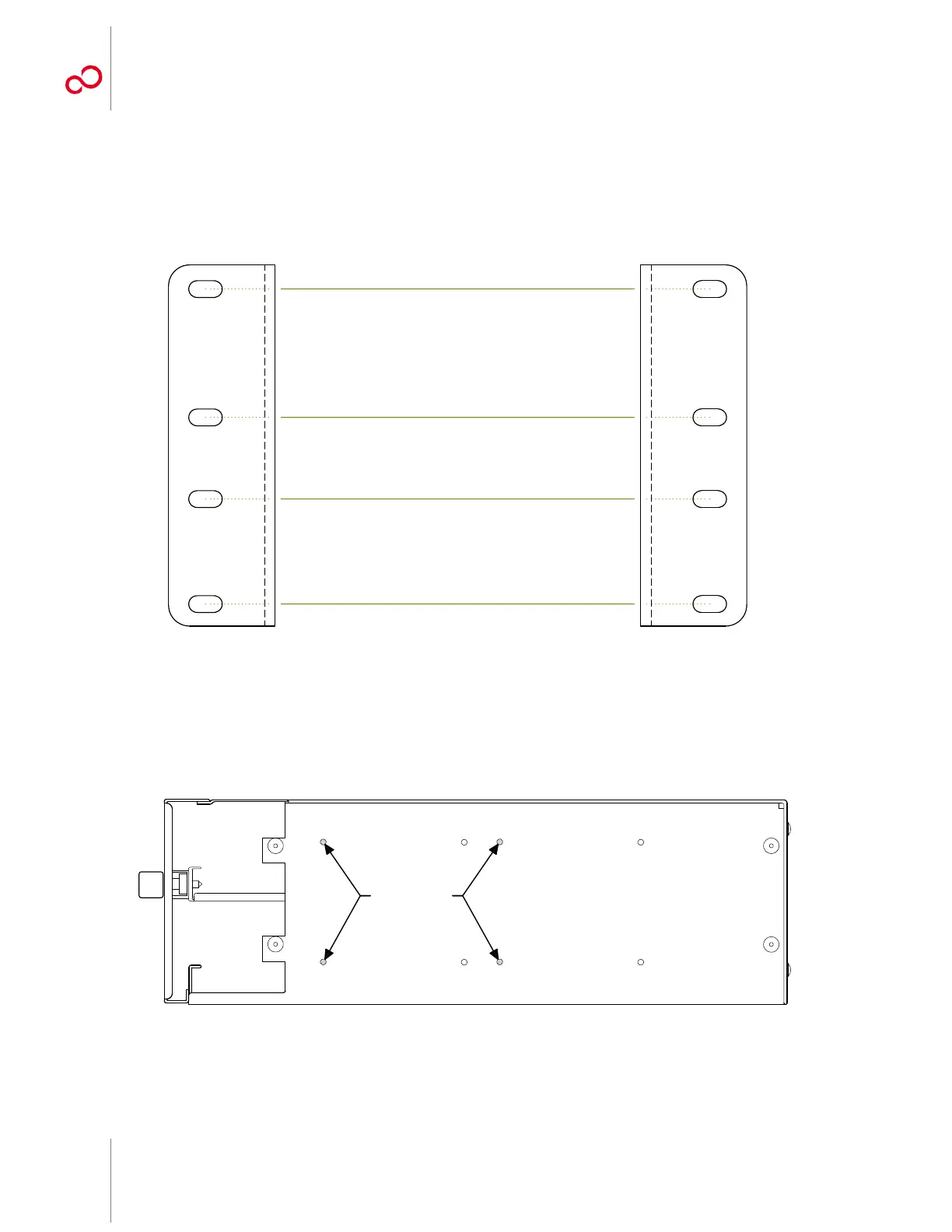
4 Identify the left and right shelf flanges. See Figure 3-50 [p. 3-64] and Figure 3-52 [p. 3-66].
Note: At first glance, the two flanges for 19-inch rack mounting appear to be identical, but they are
not. As shown in Figure 3-52 [p. 3-66], the top two clearance holes are slightly farther apart than the
bottom two clearance holes.
5 Identify the flange mounting holes for 19-inch rack installation on the side of the
FC9503LAS2 shelf. See Figure 3-53 [p. 3-66].
Figure 3-52: FC9503LAS2 Shelf Mounting Flanges (Front View)
Figure 3-53: Flange Mounting Holes on Right Side of FC9503LAS2 Shelf (19-Inch Rack Installation)
Larger Space
(Top)
Smaller Space
(Bottom)
Left Shelf Flange Right Shelf Flange
L R
m1656sm_3