SERVICING
121
PULSE Installaon, Commissioning and Servicing Manual - Revision 19
23.3 Blending Manifold
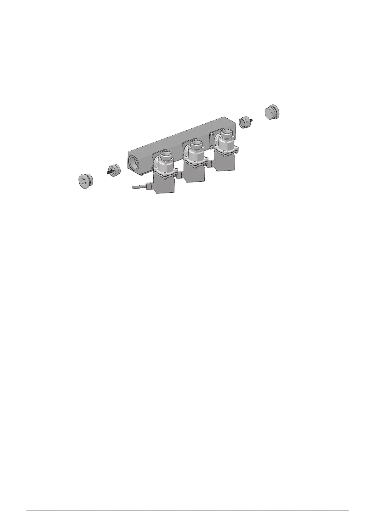
The blending manifold has 3 proportional valves attached with two non return valves. The
two “component” fuels are fed into the manifold and channelled proportionally into the
centre of the manifold to make the blended fuel.
Figure 49. Blending Manifold Assembly
23.4 WIRING
This secon describes the wiring and cable connecons specic to the blending dispenser.
Additional components used are:
− a second Integrated Stack Controller located in the head
− a second Multiplexer located in the hydraulic cabinet
− a second Barrier located in the head
− an Auxiliary Power Module
The Mulplexer Board for a parcular side is located on the right.
Compared to the wiring in a convenonal dispenser, the Auxiliary Power Module is wired
in a similar way, whereas the Mulplexer Board is slightly dierent.
23.5 Stack Controllers
Each Integrated Stack Controller has valve sockets marked P28-P22 from left.
Note: FRONT solenoid valves connect to Stack Controller 1000, (top)
REAR solenoid valves connect to Stack Controller 1100, (bottom).
non-return valve
blending manifold
solenoid valves
seal


 To Next Page