SERVICING
70
PULSE Installaon, Commissioning and Servicing Manual - Revision 19
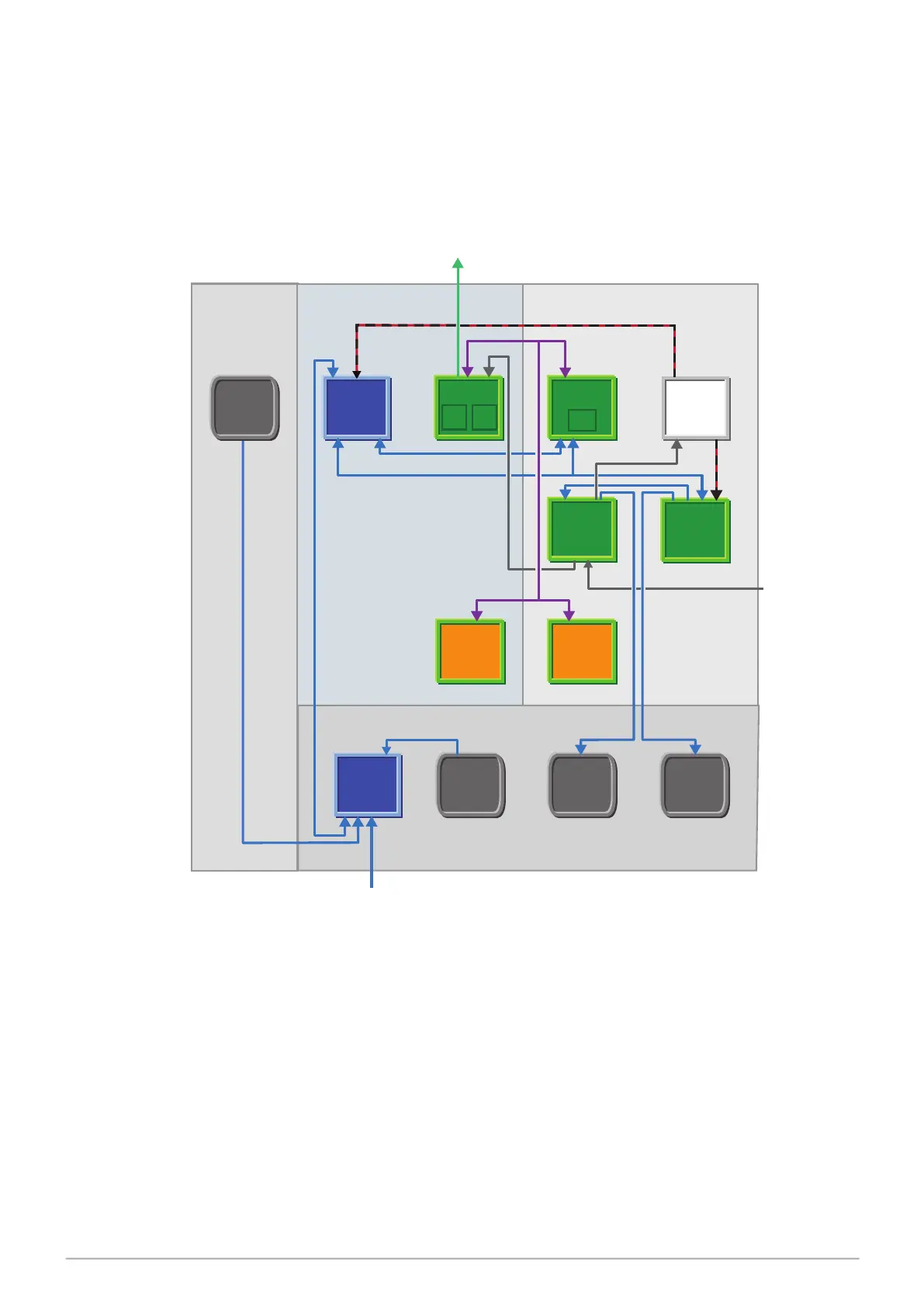
10.2 Simple Wiring Diagram
The PULSE Electronic Set Modules are interconnected for communication purposes and
power supply.
The following figure shows the connections between the different modules present in the
standard PULSE assembly.
Figure 35. Simplified Wiring Diagram
Column Head Front
Head Rear
Hydraulic Cabinet
Barrier
Module
Central
Controller
SD
Card
PSU
Stack
Controller
FRAM
Module
Solenoid
Drive
Module
Motor Drive
Module
Mulplexer
Module
24vDC
Power
Supply
User
Interface
User
Interface
Proporonal
Solenoid
Valves
Pump
Motors
Relays
Flow
Encoders
Holster
Switches/Flow
Switches (Diesel)
(Front & Rear)
Local Bus
Ethernet
Float Switch
230vAC
230vAC
24vDC
24vDC
24vDC
230vAC IN