INSTALLATION
53
PULSE Installaon, Commissioning and Servicing Manual - Revision 19
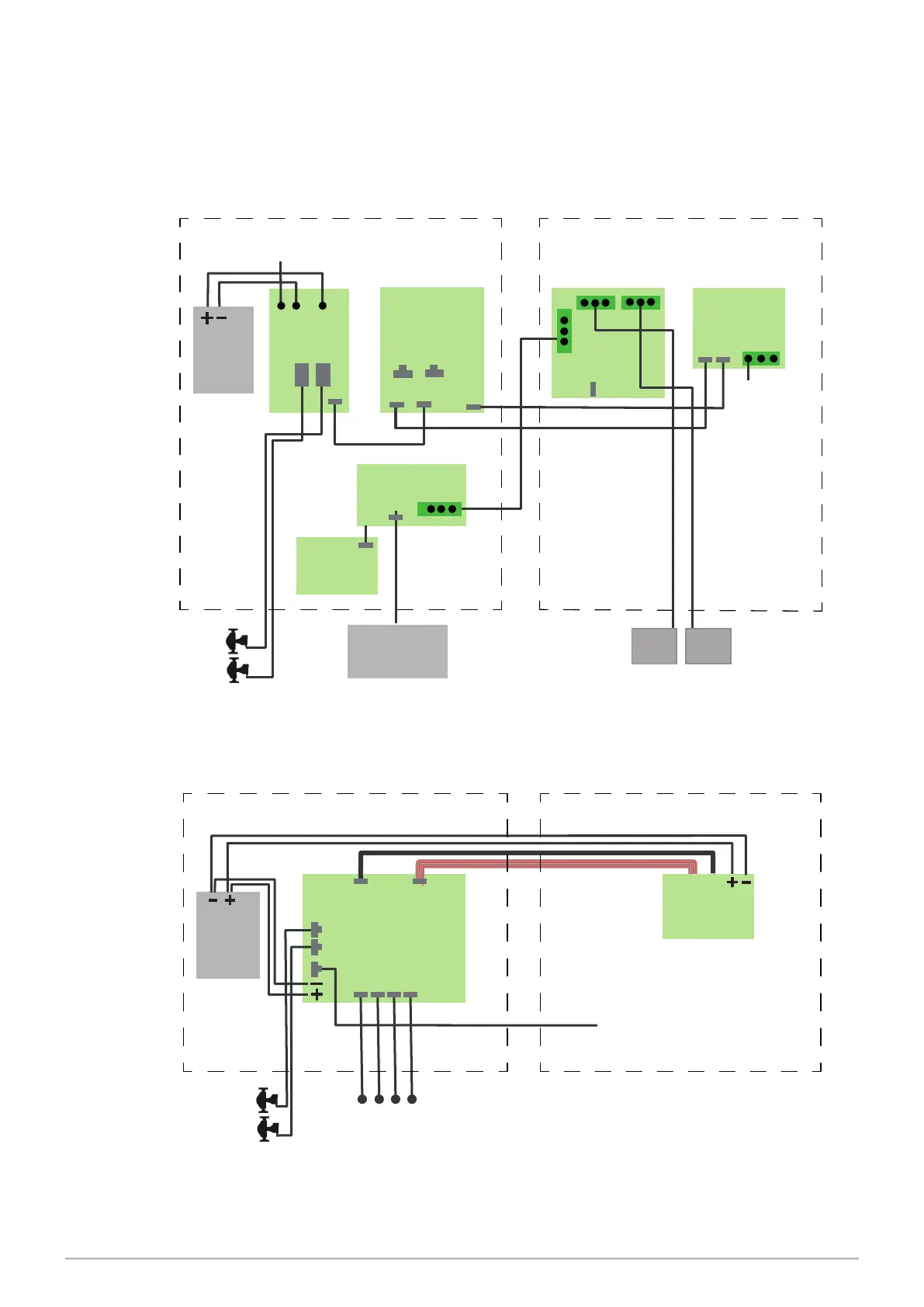
7.9 LPG Electrical Schematics
The following diagram indicates the interconnection between the various LPG components.
Figure 22 is used where other products are present. Figure 23 would normally be used for
a stand-alone LPG dispenser.
Figure 23. LPG Electrical Schematic
Figure 24. LPG Electrical Schematic Using Integrated Stack Controller
24V DC
PSU
STACK
CONTROLLER
CORIOLIS
METER
INTERFACE
MOTOR DRIVE
L E N
DC
SOLENOID
DRIVE
230VAC
from
Terminal Box
REAR GEAR PLATE
FRONT GEAR PLATE
J7 J6
E
BARRIER
AC
SOLENOID
DRIVE
2-Stage AC Solenoid Valves
FRONT REAR
E
E
Coriolis
Meters
24V DC
PSU
AC INTEGRATED
STACK
CONTROLLER
REAR GEAR PLATE
FRONT GEAR PLATE
BARRIER
(CC)
Local Bus
Solenoids
2 x 2 Way
Coriolis
Meters