INSTALLATION
16
PULSE Installaon, Commissioning and Servicing Manual - Revision 19
PART B: INSTALLATION
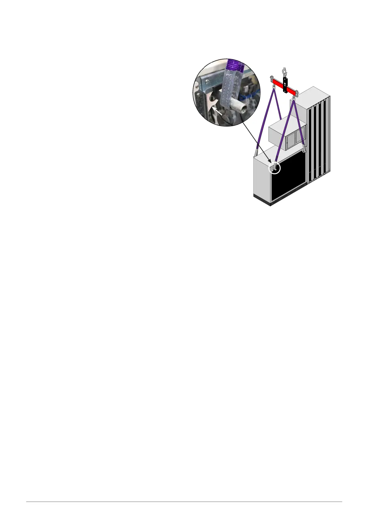
1 LIFTING OF UNITS
PULSE Fuel Delivery Systems have
brackets in each upper corner of the
hydraulic cabinet through which lengths
of 32mm (1¼”) diameter steel bar are
inserted from front to rear. Care must
be taken so as not to snag components,
wiring etc.
Suitable strops are then attached to
the ends of the bars as shown in the
accompanying diagram.
2 PRIOR TO INSTALLING
The mechanical, hydraulic and electrical work that must be completed on site prior to
installation of the dispenser is described below.
2.1 Underpump Containment Sump
Sumps with secondary containment pipework must be provided at all sites. These can be
sourced from an appropriate manufacturer.
The installation method will depend on local, legal and customer requirements.
At all sites with sumps, dispensers must be installed with a liquid level detection device
fitted in the sump that will raise an alarm if liquid is detected in the base of the sump. (see
Installation - Section 9.5 Float Switch Installation)
2.2 Hydraulic Pre-Installation
The footprint, anchor points and perimeter of the PULSE Series are contained in the
document entitled “Gallagher PULSE Series - Footprint Information.” (Part No. 2A02068)
To view this document access the following website and enter the name (eg footprint
manual) in the search window.
https://fuelsystems.gallagher.com/support
2.3 Anchoring Bases
Requirements applicable to all system sizes include:
• all anchor points must be bolted to a rigid horizontal surface (see illustration);
• bases must be fixed or anchored to a rigid and level surface. The surface that the
pump is fixed to must contact the whole of the base plate’s ‘ground’ contact surface.
The bar length should be a minimum of 750mm so that the
ends extend away from the cabinet sufficiently for strops/
ropes to be attached with no risk of slipping off.
bracket
All lifting equipment used must comply
with appropriate standards and regulations.