SERVICING
71
PULSE Installaon, Commissioning and Servicing Manual - Revision 19
PEPE
N
L
R1 R2 R3 R4 R5
Mains Supply
230/240 VAC, 10A, 50Hz
PE
Mains Earth
N
Neutral
L
Live/Phase
STP Control
Relays (L)
R4,R5
R1,R2,R3
Dispenser
Single Phase Pump
Mains Supply
230/240 VAC, 16A, 50Hz
PE Mains Earth
N Neutral
L Live/Phase
PEPE
N
L
61 2 3 4 5PE
Communications PE 1 2 3 4 5 6
2 Wire Pump Comms + -
Vapour Recovery dG dA dB SP SN
Dispenser, Single Phase Pump
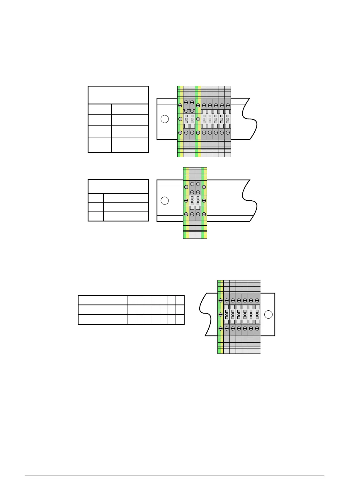
Figure 36. Mains Connections
Figure 37. Comms Connections
10.3 Junction Box Wiring Diagrams
As shown in Figure 34 the mains power supply connector block varies between a dispenser,
and a single phase pump.
POS cabling is connected into a common connector block as shown in Figure 37.