98
IIDTool
GAP Diagnostic 2023-09-12 All Rights Reserved
User Manual G3 units: Version 37, Firmware V4.0
Steps:
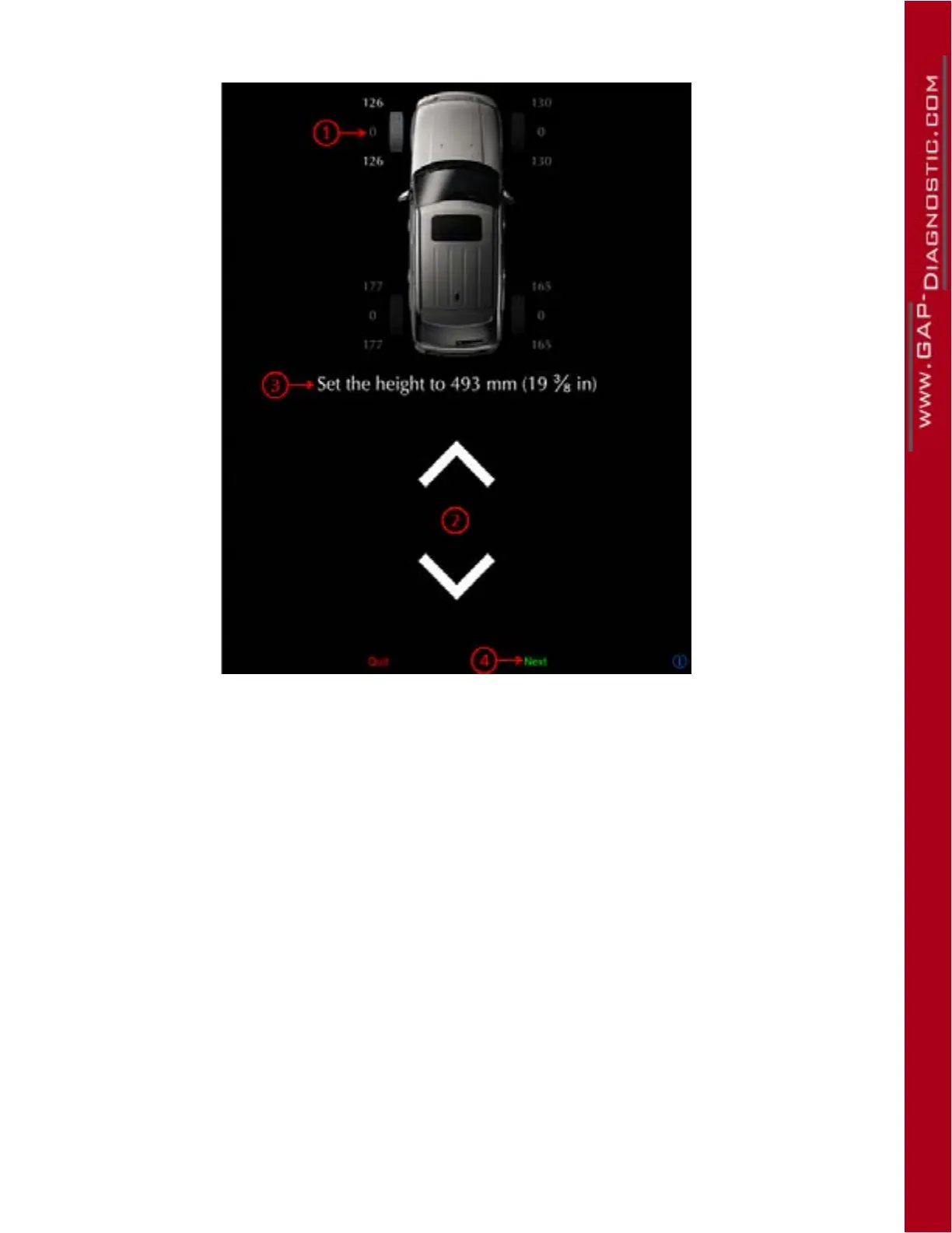
Figure 53. Guided Calibration steps
• The rst corner to be calibrated is the front left corner (1).
• Place your measuring tape as instructed and use the up and down arrows (2) to reach the requi-
red height (3).
• Once completed, click on Send (4). The next corner to be calibrated will now be highlighted.
• Repeat the previous steps for all corners.
Notes:
• It is normal for the opposite corner to move when adjusting the height of a corner. This does not
aect in any way negatively the calibration.
• It is normal for the vehicle to be crooked during calibration. Once the process is completed, the
suspension will adjust the vehicle accordingly.
• Using a fabric tape measure taped to the center of the wheel will allow operation of the App
while measuring and ensure more consistent measures.
• Depending on the vehicle and axle, it is easier to control either the up or down motion. Use the
less precise as the starting point then adjusts more precisely.
• Marking the center of the wheel does help with consistent measures.
• Calibration of all corners is done in one iteration. Once a corner is calibrated, its calibration will
no longer be aected by movements induced by other corners being calibrated.