ZP3 Fire Control Panel Installation, Commissioning and Maintenance Manual
Page 102 REV 11 (ISS 08/03/2010)
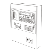
Circuit schematic
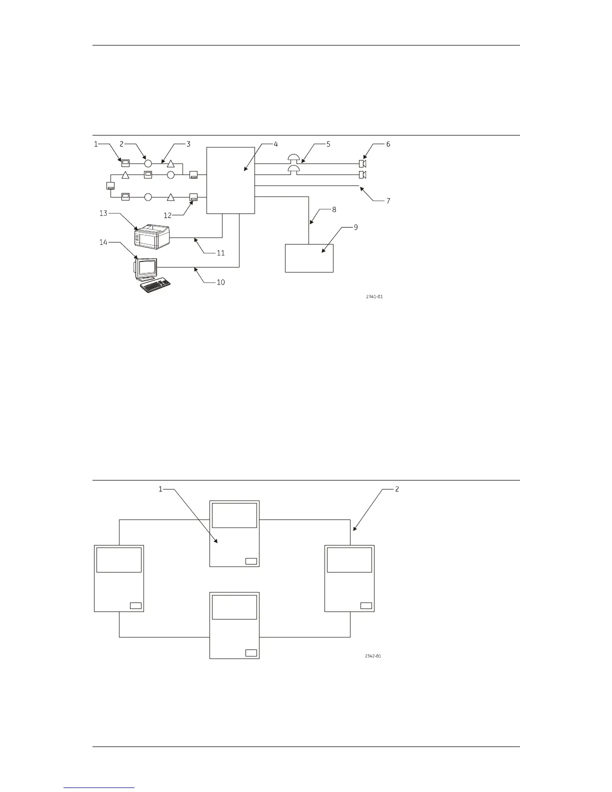
Figure 60 shows a typical single panel system, and Figure 61 shows a typical multi-panel
networked system.
Figure 60: Typical single panel system
Legend:
Item Description Item Description
1 Manual callpoint 8 Data wiring-RS485
2 Detector 9 Repeater panel
3 Z-address line 10 Data wiring-RS232
4 Control unit 11 Data wiring-serial
5 DC wiring 12 Isolator
6 Sounder 13 Printer
7 Switched output 14 Computer
Figure 61: Typical multi-panel system
Legend:
Item Description Item Description
1 Control unit 2 Communication wiring-RS485