ZP3 Fire Control Panel Installation, Commissioning and Maintenance Manual
REV 11 (ISS 08/03/2010) Page 47
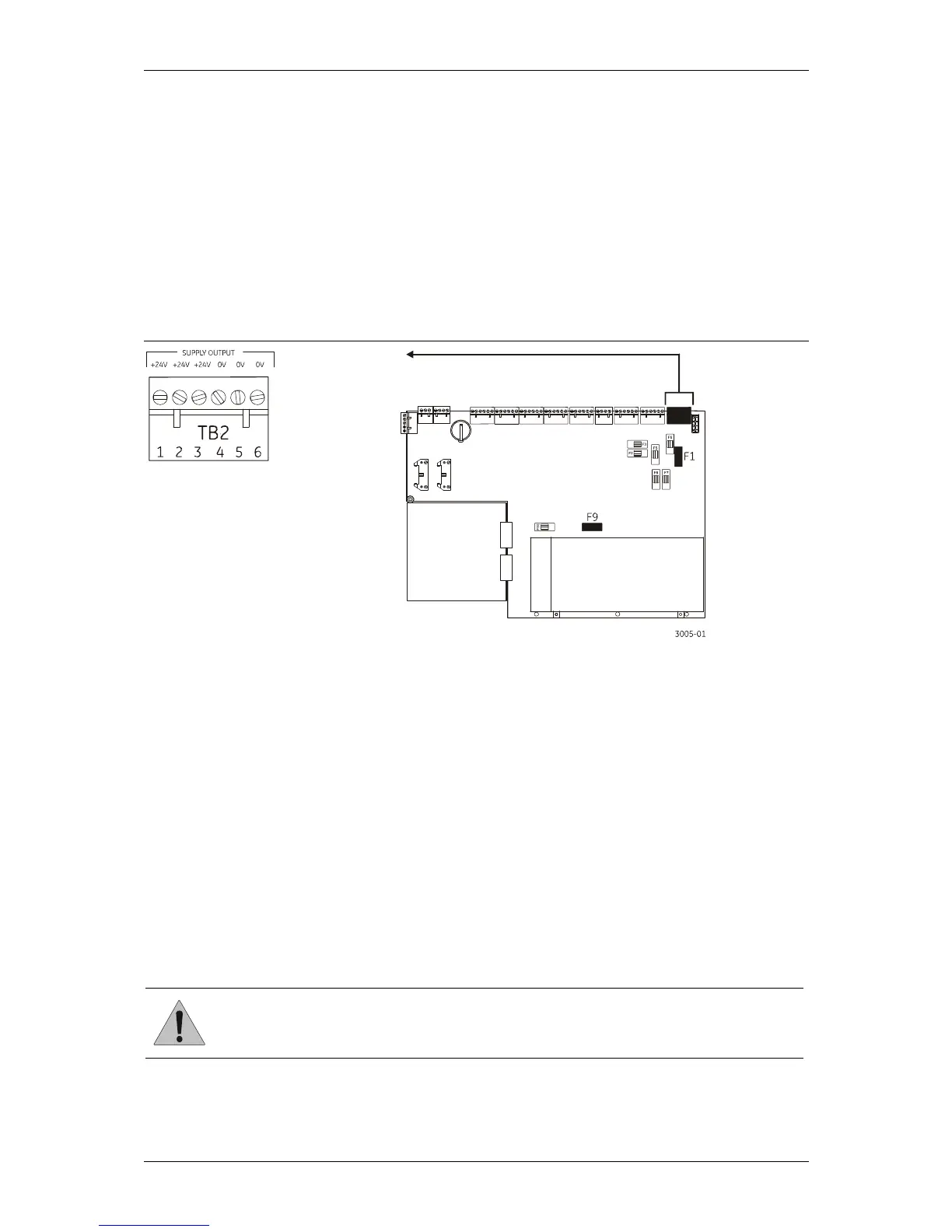
Auxiliary 24 VDC supply
See Figure 39. The 24 VDC output (“Supply Output” terminal – TB2 on the main board) is for use by
auxiliary equipment, such as programmable relay boards, sounder driver boards, etc. It can also
be used for providing power to devices such as remote display units, and similar peripheral
devices.
The current drawn from the auxiliary supply is a function of the system engineering. It depends
upon the load that has been allocated to the control panel for devices such as loop sounders,
common sounders, and control relays.
The output is fused at 5 A (Fuse F1).
Figure 39: Auxiliary 24 VDC supply
External power for accessory boards
Where the load required for optional accessory boards exceeds the capacity of the ZP3 power
supply, it is possible to power these boards from a separate external 24 VDC power supply as
shown in Figure 40. This external supply must meet the following criteria:
Output voltage must be in the range 22 - 28 VDC.
Output ripple must be a maximum of 200 mV (peak-peak).
Output ripple with full load must be a maximum of 500 mV peak.
Must comply with the requirements of European Standard EN54-4.
Output capacity must be adequate for the required load, even with batteries disconnected.
Incorporate standby batteries, sized to provide the required operating period.
The output must be suitably fused.
For reporting faults to the ZP3 fire panel, two voltage-free changeover contacts must be
provided, one signalling a mains failure, the other signalling a battery fault.
CAUTION:
Do not connect the 0-volts (negative supply) of the external power supply and the 0-
volts (negative supply) of the fire panel. The two power supply systems must remain
floating from each other.