ZP3 Fire Control Panel Installation, Commissioning and Maintenance Manual
REV 11 (ISS 08/03/2010) Page 13
Door assembly
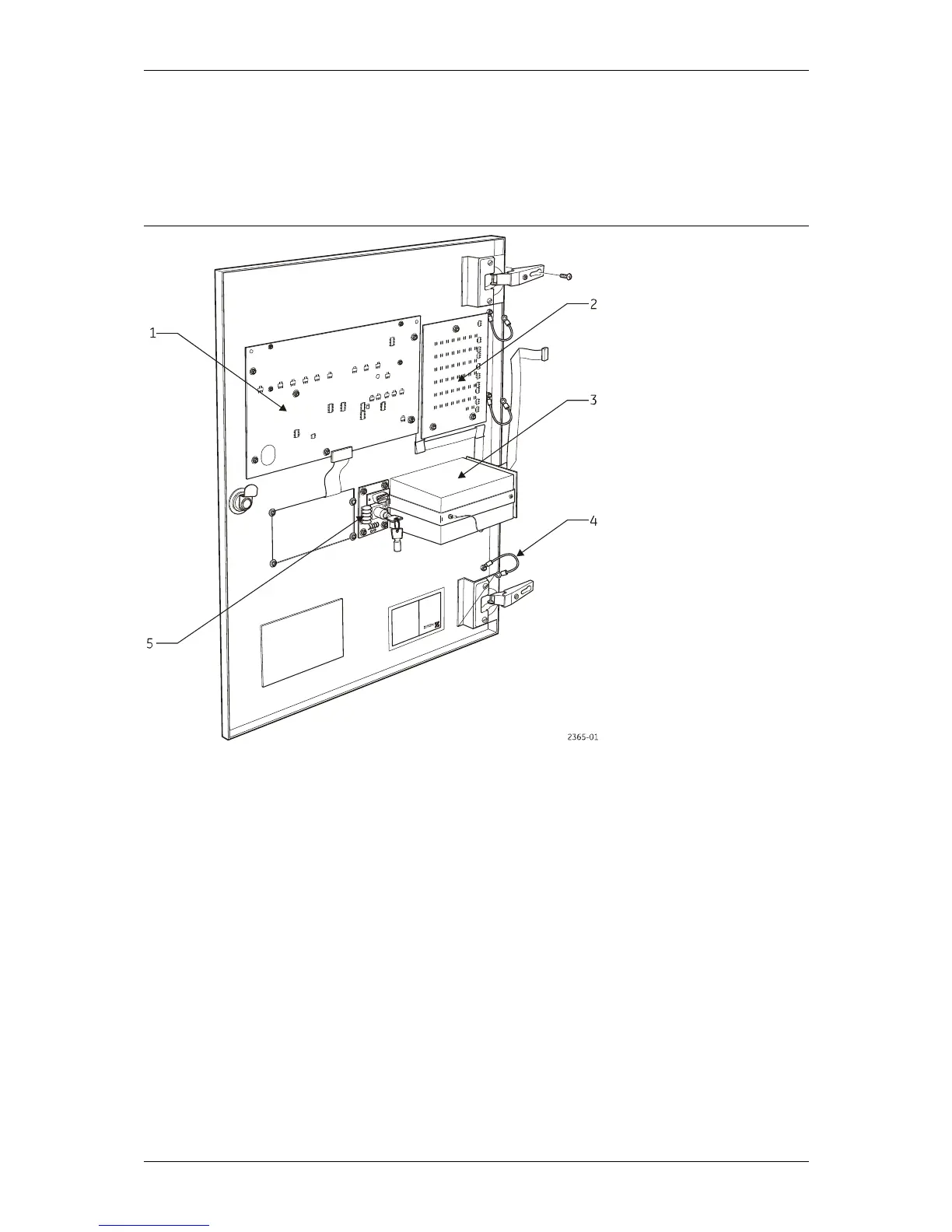
Figure 7 shows all the main features of the ZP3 panel Door Assembly. This unit comprises the
panel display and control electronics as well as the keyboard, a serial connection for data
loading, and the printer (if fitted).
Figure 7: ZP3 Fire Control Panel - Door Assembly
Legend
Item Description Item Description
1 Display board 4 Earth straps
2 Zone board 5 Commissioning board
3 Optional printer
Remove the complete door assembly if required as follows:
1. Remove two (2) screws securing the hinges.
2. Remove the four (4) nuts securing the earth straps, which connect from door to box.
3. Carefully unplug cables connecting the door boards to the main chassis.
Note: Do not dismantle the door boards. There are no field serviceable parts in the assembly.