ZP3 Fire Control Panel Installation, Commissioning and Maintenance Manual
Page 12 REV 11 (ISS 08/03/2010)
Legend:
Item Description Item Description
1 Earth monitoring enabled 20 Monitored sounder 2
2 Battery for time/date 21 Main 24 VDC power 6.3 A
3 Chassis 22 5 VDC power 0.5 A
4 Field terminals 23 Charge rate selector
5 LED 6 RMC alarm activated 24 Power supply unit
6 LED 10 RMC fault activated 25 CPU board
7 LED 12 common fire 26 LED 4 mains on
8 LED 11 common fault 27 LED 2 RDU +ve
9 LED 13 sounder 1+2 activated 28 LED 7 RS232 +ve
10 LED 36 sounder 3+4 activated 29 LED 8 RS232 -ve
11 LED 1 battery charging 30 LED 14 +5V_S
12 LED 5 RMC alarm overload 31 LED 15 +5V
13 LED 9 RMC fault overload 32 LED 37 24V
14 Monitored sounder 4 33 LED 20 sounder fault
15 Monitored sounder 3 34 LED 19 loop fault
16 Aux/supply out 35 LED 18 earth fault
17 RMC fault alarm 36 LED 21 ADC failure
18 Battery/external 24V 37 To auxiliary boards
19 Monitored sounder 1 38 To display PCB
The main chassis is removed from the panel by removing the four (4) securing screws.
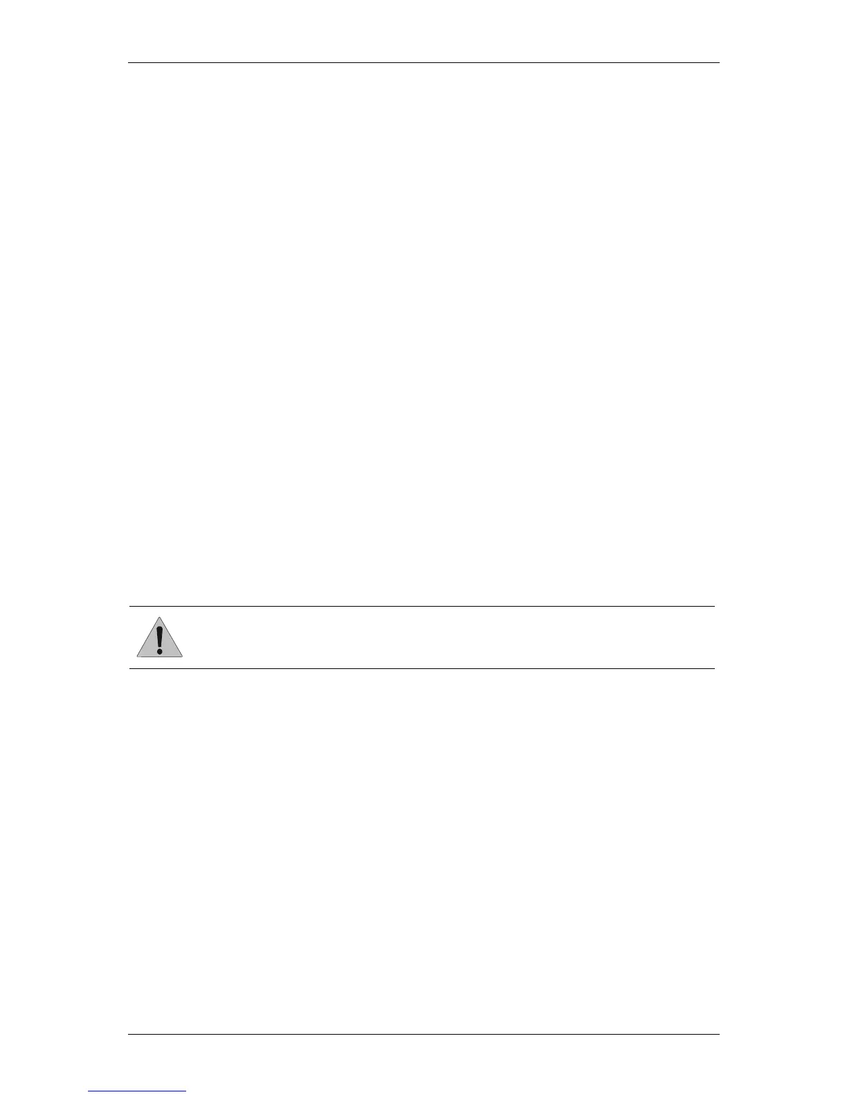
CAUTION:
Once removed, the main chassis should not be dismantled, as very high voltage exists
below the circuit board, and can be present even when mains is off, or the unit is
removed from power. There are no field serviceable parts in the assembly.