ZP3 Fire Control Panel Installation, Commissioning and Maintenance Manual
REV 11 (ISS 08/03/2010) Page 27
Installing the modem
WARNING:
TO PREVENT ELECTRIC SHOCK, DO NOT REMOVE THE COVER OF THIS MODULE WHILE
UNIT IS POWERED UP. THERE ARE NO USER-SERVICEABLE PARTS INSIDE. ONLY AN
APPROVED MAINTENANCE AUTHORITY MUST DO SERVICING.
Install the Modem as follows:
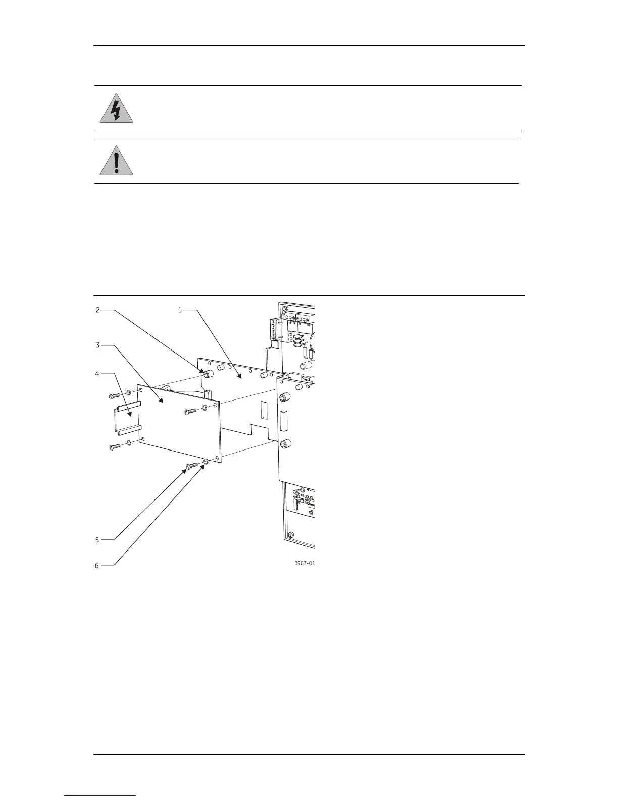
Note: Make sure the associated washers are positioned directly beneath each screw head.
1. See Figure 21 below. Fit the Modem mounting bracket (item 3) onto the four accessory plate
stand-offs (item 2) and secure using the four M4 screws (item 5) supplied, with associated
washers (item 6) positioned directly beneath each screw head.
Figure 21: Installing the modem mounting bracket
2. See Figure 22 on the next page. Position the Modem on the mounting bracket so that the
Modem catch is positioned in the upper tab of the mounting bracket.
CAUTION: Do not over-tighten the panel clamp screws. Failure to comply will damage the unit.