ZP3 Fire Control Panel Installation, Commissioning and Maintenance Manual
Page 28 REV 11 (ISS 08/03/2010)
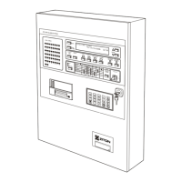
Figure 22: Installing the modem
3. Push the lower corner of the Modem in the direction of the arrow so it locks into position on
the mounting bracket.
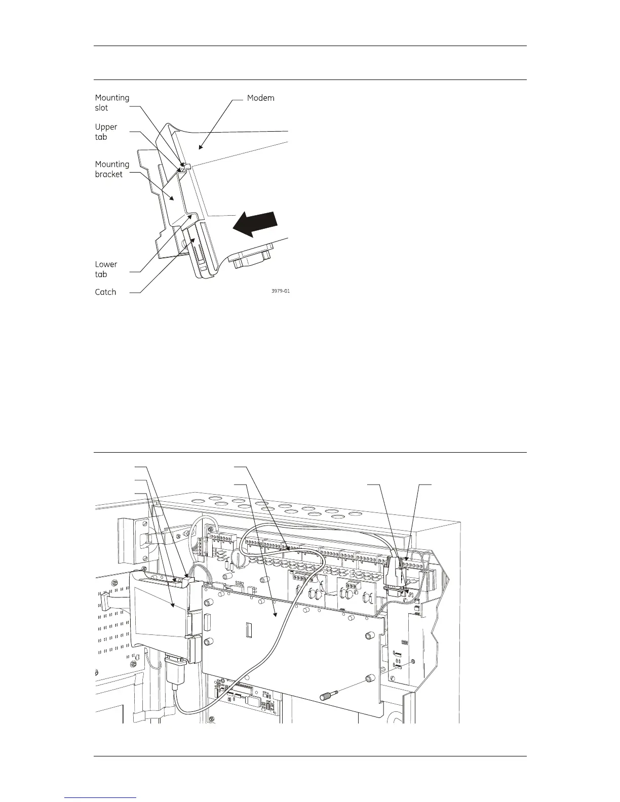
4. See Figure 23 below. Fit the accessory plate (if necessary) to the ZP3 panel.
5. Connect the 9-way RS232 cable from the Modem connector to connector JP3 on the ZPAB-
RS232 board located on the ZP3 panel.
6. Connect the telephone line to the RJ11 socket on the Modem.
7. Connect +24 VDC supply from the Modem power supply connector to the +24V and 0V
connections on the Supply Output connector located on the ZP3 panel main board.
Figure 23: Installing the accessory plate and connecting the RS232 and power cabling
3886-0