ZP3 Fire Control Panel Installation, Commissioning and Maintenance Manual
Page 20 REV 11 (ISS 08/03/2010)
The parameters are dependent on the programme used. The following options are available:
Parameter Remarks
Z-PORT Enter Z-port number [1]
Protocol Enter the required protocol as follows:
[0] to disable the port
[1] ZCP2 protocol, multi-telegram, full handshaking
[2] ZCP2 protocol, single telegram, single direction TX only, no handshaking
[7] ZCP2 protocol, single telegram, full handshaking
[11] ZCP3 for use with Ziton Planner
[18] ZCP2-3 protocol, multi-telegram, full handshaking (configurable). For use with Ziton
Planner, Maestro & Building Management systems
Setup Enter the required setup data from the following options:
Baud rate = 57600, 38400, 33600, 28800, 19200, 14400, 9600, 4800, 2400, 1200, 600, 300
Data bits = 5, 6, 7, 8
Parity = Even, Odd, None
Stop bits = 1,2
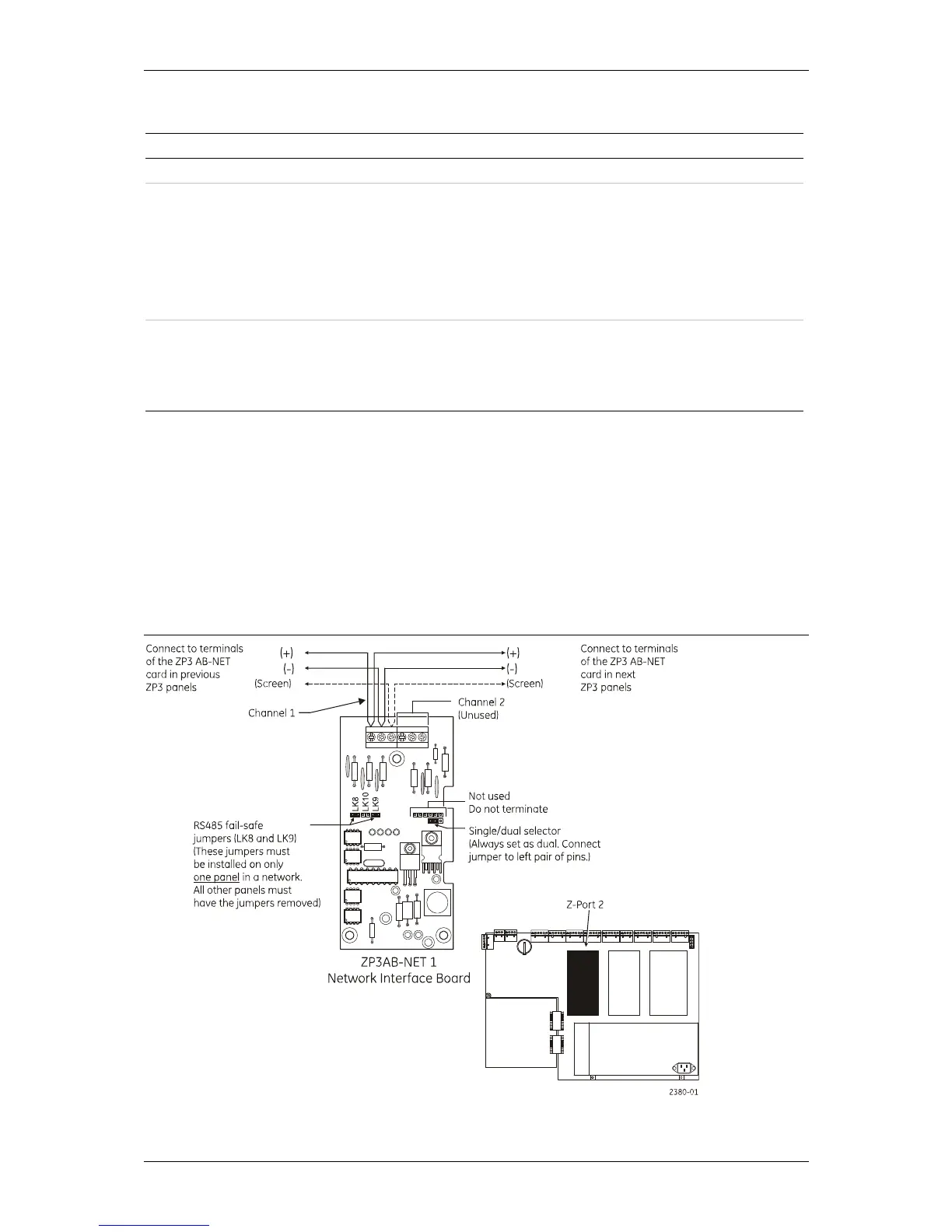
ZP3AB-NET1 Network board (Z-Port 2)
This board is used to connect a number of ZP3 panels into a peer-to-peer network. The hardware
protocol is a multi-drop RS485 screened two-wire connection. Although the ZP3AB-NET1 board is
capable of dual routing operation, ZP3 software does not support this feature, and the board
must be used as a single-channel device. In a network of ZP3 panels, one of the panels must have
the fail-safe links connected by connecting the jumpers as shown in Figure 15. All other panels
must have their jumpers removed. For long cable runs wiring should be terminated (using LK10)
at each end of the cable run, in addition to the LK8 and LK9 jumpers. In any case no more than
two terminating links (LK10) must be inserted.
Figure 15: ZP3AB-NET1 Network board (Z-Port 2)