[EN] English - K0460 Pressure indicator operation (MC 620-IS) 4-1
Chapter 4: Pressure indicator
operation (MC 620-IS)
4.1 Introduction
This section gives examples of how to connect and use the
instrument to measure pressure with the module carrier
(MC 620-IS) and the applicable pressure modules (PM 620-IS).
To measure pressure with the IDOS UPM, refer to Chapter 3.
To make a fully integrated pressure calibrator instrument with
one of the three pressure stations, refer to the user manual for
the PV 62x-IS series of pressure stations - K0462
Before starting:
• Read and understand the “Safety” section.
• Do not use a damaged instrument.
Note: Use only original parts supplied by the manufacturer.
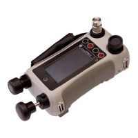
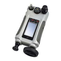
4.2 Parts and
assembly
This figure shows the parts of the module carrier (MC 620-IS)
and pressure module (PM 620-IS).
After attaching these items to the DPI 620-IS calibrator, a fully
integrated pressure indicator is formed that can measure
pneumatic or hydraulic pressure.
Caution: To prevent damage to the PM 620-IS, use
within the specified pressure limit on the label.
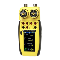
1. Pressure connection (G1/8 or 1/8NPT) to attach
external pressure equipment.
2. Pressure and electrical connections for a pressure
module (PM 620-IS). These are self-sealing
pressure connections.
3. Two screws to attach the calibrator (DPI 620-IS).
4. Electrical connections for the calibrator
(DPI 620-IS).
5. Pressure module (PM 620-IS) with a pressure
connection, reference port (a) and a label. The
label includes:
Pressure range. Example: 20 bar g (g: gauge;
a: absolute); serial number (S/N); manufacturer:
name, address, website.
 Loading...