Issue 1
4-6 Pressure indicator operation (MC 620-IS) K0460 - [EN] English
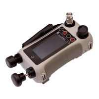
1. Assemble the pressure indicator with the correct PM 620-IS
modules; see Section 4.2.1.
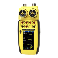
2. Set the applicable software options; see Section 4.4.1
(Procedure overview). This example shows two pressure
functions:
• Pressure functions P1 and P2 are set-up.
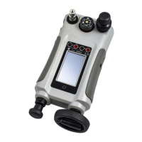
3. To attach the external equipment, see Section 4.3.1.
4.5 Error indications
If the display shows <<<< (under range) or >>>> (over range):
• Make sure that the range is correct.
• Make sure that all the related equipment and connections
are serviceable.
<<<<< Under range: The display shows this symbol for this condition:
Reading < Negative FS - (10% of negative full-scale).
>>>>> Over range: The display shows this symbol for this condition:
Reading > Positive FS + (10% of positive full-scale).
 Loading...