Issue 1
10-14 Calibration procedures K0460 - [EN] English
10.14 Procedures:
Pressure indicator
modules (PM
620-IS)
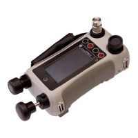
1. Assemble the pressure indicator with the necessary
PM 620-IS modules and connect the instrument to the
pressure standard; see Section 4.4.4 (Example procedure:
Measure pressure).
2. Let the equipment get to a stable temperature (minimum:
60 minutes since the last power on).
3. Use the calibration menu (Section 10.3) to do a two-point
calibration (Zero and +FS) or a three-point calibration (-FS,
Zero and +FS). Refer to Table 10-13.
4. To make sure the calibration is correct, select the applicable
pressure function; see Section 4.4.4, and apply these
pressure values:
• Ranges g: 0, 20, 40, 60, 80, 100 (%FS)
Then: Go back to 0 in the same steps.
Then (three-point calibration only):
-20, -40, -60, -80, -100 (%FS)
Then: Go back to 0 in the same steps.
• Ranges a: 0, 20, 40, 60, 80, 100 (%FS)
Then: Go back to 0 in the same steps.
Table 10-13: Calibration pressures
Ranges: g Nominal applied pressure
mbar (psi)
-FS † Zero +FS
≤ 700 mbar (10.0 psi) -FS 0 +FS
> 700 mbar (10.0 psi) -900 (-13.1) 0 +FS
† For a three-point calibration, do not apply more than -90% of
the specified FS for the unit.
Ranges: a
Nominal applied pressure
mbar (psi)
Zero +FS
350 mbar (5.00 psi) < 1.0 (0.02) +FS
2 bar (30.0 psi) < 5.0 (0.07) +FS
7 bar (100.0 psi) < 20.0 (0.29) +FS
20 bar (300.0 psi) < 50.0 (0.73) +FS
≥ 350 bar (5000 psi) Use atmospheric
pressure as zero.
+FS
 Loading...