GE MEDICAL SYSTEMS
DIRECTION 2380207, REVISION 7 LOGIQ™ 5 PRO SERVICE MANUAL
8 - 38 Section 8-4 - Keyboard Block
8-4-11-4 Removal Procedure (cont’d)
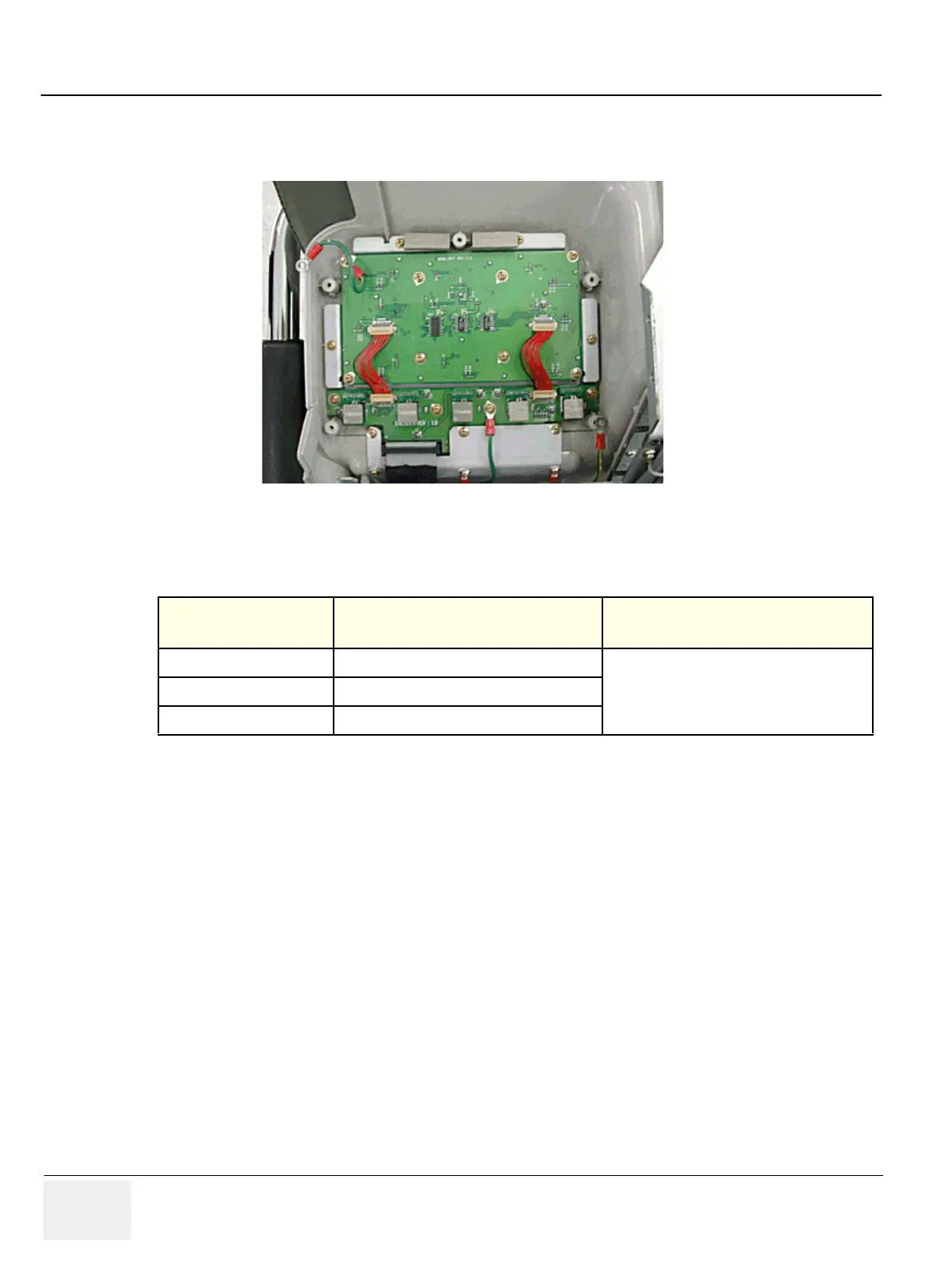
2.) Disconnect two connectors and unscrew 8 screws. Refer to Figure 8-40.
3.) Perform the following functional tests. If all are successful, include the debrief script provided below.
8-4-11-5 Mounting Procedure
Install the new parts in the reverse order of removal.
Figure 8-40 Unscrew 8 screws
Table 8-18 Functional Tests
Service Manual
Section
Functional Test / Diagnostic Test Debrief Script
Section 4-3-1
Power On/Boot Up
“Service Manual, Direction
2380207, Rev 7+, Section 8-4-11.
Equipment passed all required tests and is
ready for use. “
Section 4-3-2
Power Off / Shutdown
Section 4-11-10
Menu Key Assy
12
34
5
67
8
12
34
5
67
8
 Loading...