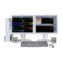
Equipment overview
2026419-033E CIC Pro™ 2-5
Connectors, ports and switches
Item Function
1 Equipotential stud Connect a ground wire from another device to ensure the devices share a common reference
point.
2 Ventilation opening Vent internal processor heat to the outside of the processor box.
3RX
S/5
Do not use this port or connect to any device. This port is physically disabled by a dummy plug.
4 CARESCAPE Network MC
network connection
Interface with other networked GE patient monitoring and telemetry system devices.
Display waveform, parameter, and alarm condition data from other networked devices.
5 CARESCAPE Network IX
network connection
Provide ability to display full disclosure data.
Access remote serviceability.
Connect to an optional network laser printer.
Connect to an optional Citrix server.
Connect to an optional web browser.
6 RS232 2 connector Connect to the PRN 50-M digital writer.
7 RS232 1 connector Connect to the serial touchscreen display.
8 DVI-I 1 video connector Connect to the primary display.
9 DVI-D 2 video connector Connect to an optional secondary display.
10 USB ports There are six USB ports you can use to connect the following devices:
Standard mouse.
Standard keyboard.
Touchscreen display.
USB memory stick (used to activate CIC Pro center licenses and other servicing functions).
USB printers.
11 External speaker connector Connect to external speakers to hear patient and system status alarm notification.
12 Power switch Press to turn on or to turn off.
13 Power connector Connect the power cable.
14 Power indicator Illuminates when powered on.
15 Speaker opening Permits internal speaker to sound externally.
16 IP address labels Identifies the IP address of this device on the respective networks.
NOTE
The CIC application does not use the S/5 network,
17 Serial number label Identifies the serial number of the device.
18 Power clamp Provided to clamp the power cord and speaker.