GE COMPANY
DIRECTION 5472001-1EN, REVISION 6OPTIMA CT680 SERIES AND OPTIMA CT670 INSTALLATION MANUAL
Page 36 Section 4.0 - Layout the Floor Template
Figure 1-2 Gantry Tube Change Cart
5.) Prior to removing this template, check floor levelness, as shown in Figure 1-3.
6.) Position the laser from the install kit on the template behind the table base and turn it on to
project a horizontal beam across the floor template area.
7.) Measure the distance from the floor to the laser line at each bolt hole location on the template
and record the measurements. Use the measurements to verify the floor is within specification.
The floor must meet the minimum levelness specification: 6 mm (1/4 in.) over 3.5 m (10 ft.)
between the table and gantry.
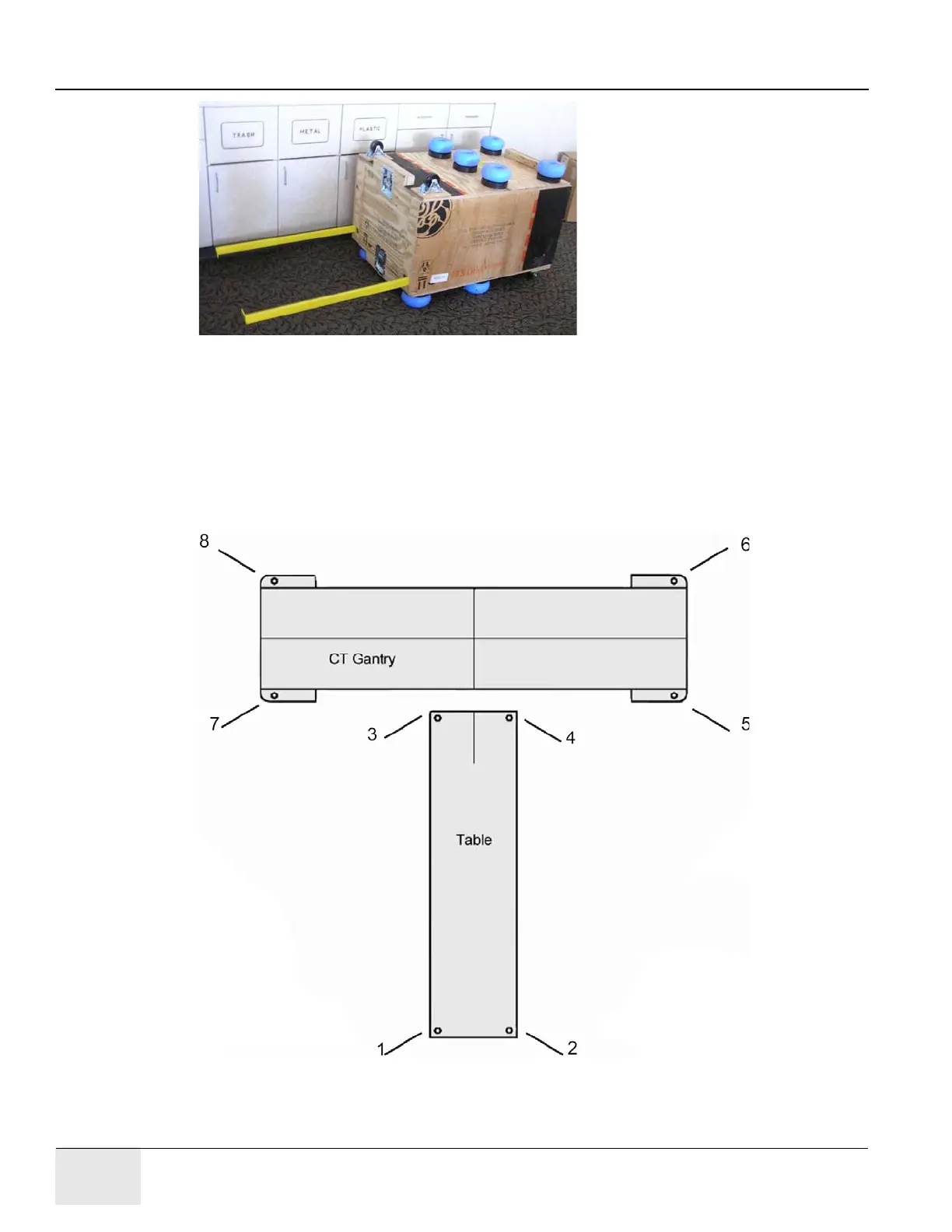
Figure 1-3 Check Floor Level
Each number represents an anchor point.
Each anchor point must be within a ¼"
(6 mm) approximate height of each other.

 Loading...


