EasyManuals Logo

GW Instek PSW Series User Manual

GW Instek PSW Series
184 pages
To Next Page IconTo Next Page
To Previous Page IconTo Previous Page
Page #135 background imageLoading...
Page #135 background image
ANALOG CONTROL
135
External Operation and Status Monitoring
Background
The MIL 26 pin connector can also be used to
monitor the status operation and alarm status
of the instrument.
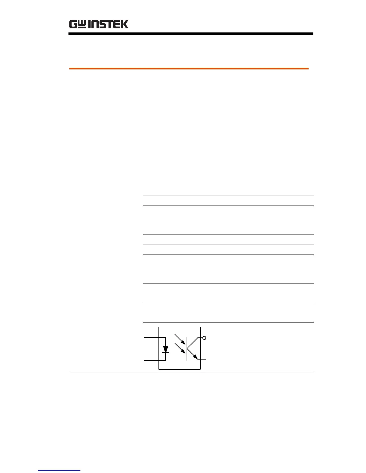
The pins are isolated from the power supply
internal circuitry by photo couplers. Status
Com (Pin 17) is a photo coupler emitter output,
whilst pins 18~22 are photo coupler collector
outputs.
A maximum of 30V and 8mA can be applied to
each pin.
Name and Pin
Description
STATUS COM
17
Common (photo coupler
emitter) for status signals 18,
19, 20, 21 and 22.
CV STATUS
18
Low when CV mode is active.
CC STATUS
19
Low when CC mode is active.
ALM STATUS
20
Low when any of the protection
modes are tripped (OVP,
OCP). Active low.
OUT ON
STATUS
21
Low when the output is on.
PWR OFF
STATUS
22
Active low.
17
Pins 18, 19, 20, 21, 22

Table of Contents

Other manuals for GW Instek PSW Series

Questions and Answers:

Question and Answer IconNeed help?

Do you have a question about the GW Instek PSW Series and is the answer not in the manual?

GW Instek PSW Series Specifications

General IconGeneral
Ripple & Noise (CC)≤ 3mArms
ProtectionsOVP, OCP, OTP
Remote SenseYes
ProgrammableYes
Operating Temperature0°C to 40°C
Storage Temperature-20°C to 70°C
Voltage Resolution1mV
Current Resolution1mA
Current Accuracy±0.1% + 10mA
Ripple & Noise (CV)≤1mVrms
Load Regulation (CC)≤0.1% + 5mA
Line Regulation (CC)≤0.1% + 5mA
Remote InterfaceUSB, RS232
DisplayLCD

Related product manuals