FR6822+ Frames
Installation and Operation Manual
3
Copyright © 2008-2011, Harris Corporation
Figure 1-1 FR6822+ Frame Front Panel
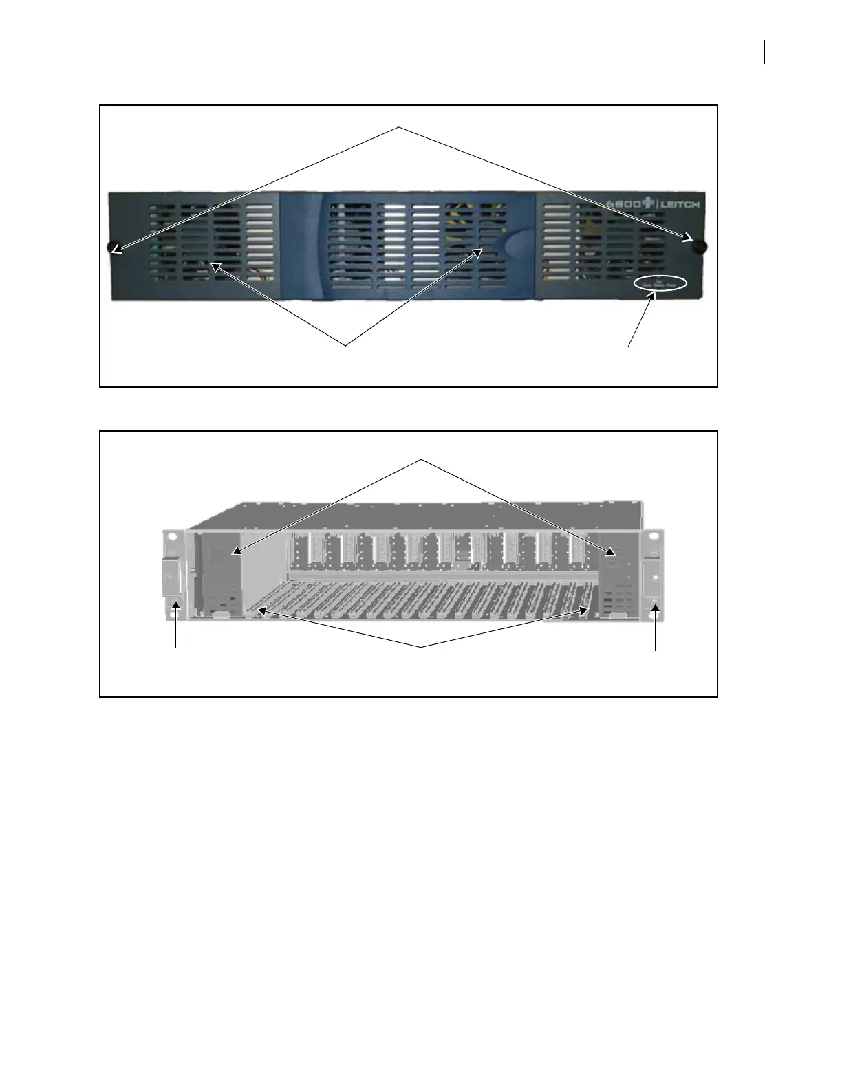
Figure 1-2 FR6822+ Frames Frame with Front Panel Removed
Rear Panel
Figure 1-3 identifies the location of FR6822+ rear panel components. Table 1-1 briefly
describes each of the connectors and switches found on the rear panel. See Making
System Connections on page 22 for more information on system connections.
Cooling fans
(built into front panel)
Finger-release screws
Status LEDs
Cooling Failure/Alarm/Power
Redundant power supplies
Front
mounting ear
20 single-slot 6800/
6800+ card guides
(floor and roof)
Front
mounting ear