Chapter 2
Installation
22
Copyright © 2008-2011, Harris Corporation
Making System Connections
Connecting
to a Power
Source
Depending on the power supply you are connecting to, choose one of the options below:
AC: A supply of 90 to 240 V AC, 47 to 63 Hz is required for both PSUs. Connect one
end of the power cable to an IEC power connector at the back of the FR6822+ frame.
Plug the other cable end into a grounded electrical source. (Repeat this procedure for
the redundant power supply using an independent power source.)
Note: Ensure that a different electrical source is used for each power supply. This ensures
true power system redundancy.
DC: A supply of 36 to 72V DC is required for each DC power supply. The DC power
supply connector has two spade terminals. You will need to connect the spade
terminals to an appropriate power source connector.
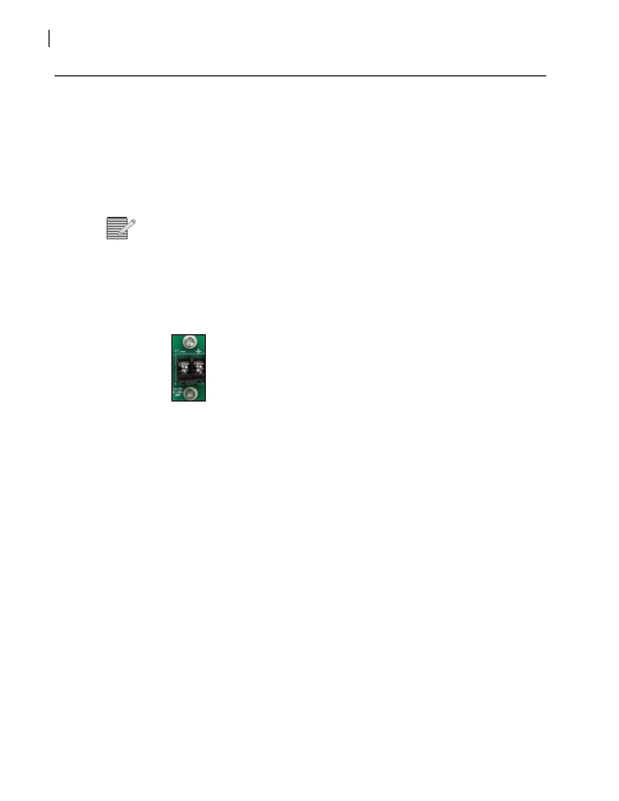
To connect the DC power supply, follow these steps:
a Open the flap that covers the screw connectors on the DC power supply.
Figure 2-14 Open Flap on DC Power Supply
b Connect the positive end of the spade connector to the + screw, and the negative end
to the - screw.
c Tighten the screws in place.
d Close the flap cover over the two screws.
e Plug the (customer-provided) cable end into a grounded electrical source.
Repeat this procedure for the redundant power supply using an independent power source.
A Power switch is located on the front face of each power supply. Before operating the
frame, ensure that both PSUs are turned on to ensure full redundancy.
Making Genlock Connections for Signal Synchronization
The genlock connectors on the FR6822+ frame provide an input path for the genlock
signal, and have a loop-through capability. (See Figure 1-3 on page 4 for the location of
the genlock loop through.)
To make genlock connections for signal synchronization, connect the reference signal to
one of the genlock loop-through BNC connectors on the FR6822+ frame. The other
connector can be used to route the reference signal to other locations. Terminate the
reference signal at its final routed location.