Chapter 1
Introduction
4
Copyright © 2008-2011, Harris Corporation
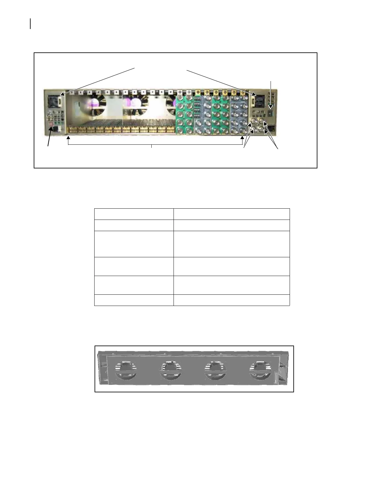
Figure 1-3 FR6822+ Frame Rear Panel
Fan
Assembly
A fan assembly is located in the front panel of an FR6822+ frame (see Figure 1-4). The fan
assembly draws in air from the front of the unit, and expels it through the back.
Figure 1-4 Fan Assembly (Back View of Front Panel)
All fans are equipped with RPM monitoring circuitry. Either the standard 6800+RESC
resource module or the 6800+ETH Ethernet resource module (described in 6800+ETH
Resource Module on page 5) decodes and monitors these signal to determine fan health.
Local and remote alarms report undesirable conditions that may arise.
Features of the FR6822+ fan assembly include the following:
Low fan-noise emissions
Frame ID
rocker
switch
Genlock loop
through BNCs
Power mains inlets
(one for each redundant PSU)
Rear module
connectors
Communication
loop through
BNCs
GPI
connector
Ethernet
connector
Table 1-1 Rear Panel Components
Item Description
Power mains inlets Independent power source connections
GPI connector Alarm relay connection between an
FR6822+ frame and a third-party control
monitoring system
Frame ID rocker switches Unique frame identification switch (four
possible frame ID combinations)
Communication loop
through BNCs (COM LOOP)
Communication network input/output
serial connections for chained frames
Genlock loop through BNCs Video synchronization connections