Chapter 2
Installation
12
Copyright © 2008-2011, Harris Corporation
Installing the Frame in a Rack
The FR6822+ frame is designed to mount into a standard-width 19-in. (483-mm) rack and
occupies a vertical space of 2RU.
Frames are secured to the rack with standard front-mounting ears built into the chassis.
Ensure you have provided adequate space behind the mounting ears, and appropriate
clearance for the connecting cables at the rear of the frame.
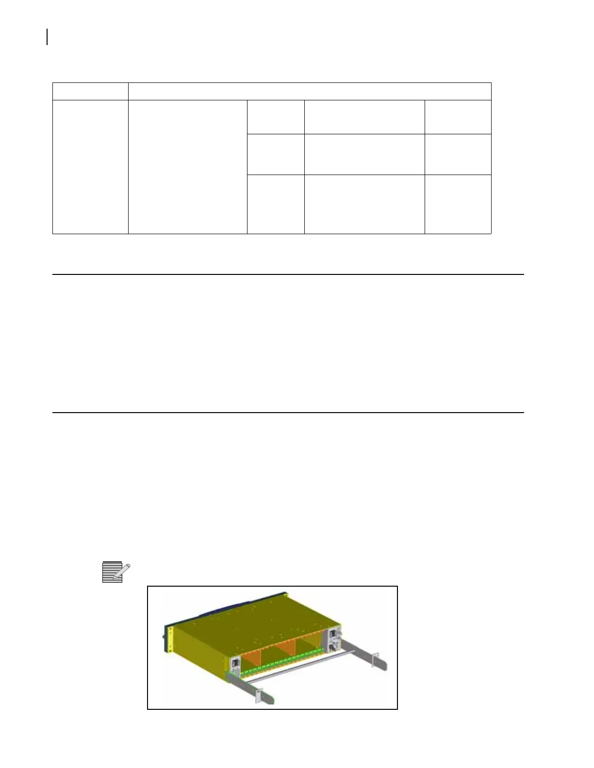
Attaching Optional Rear-Support Brackets
During normal operation, the frame’s front mounting ears provide sufficient support for the
frame. However, in some circumstances, the front mounting ears may not be sufficient to
support the entire weight of the frame and the cables attached to it. These circumstances
may include:
When using heavy breakout cables
Where the frame is exposed to motion
In order to protect the frame and the modules installed within it, you may choose to add
rear brackets to the frame.
Note: For mobile deployment of frames, rear mounting brackets are mandatory.
Figure 2-1 Frame With Rear-Support Bracket
Maximum
Power
Dissipation
These ratings refer to the
total module power
consumption (excluding
that of the power supply)
allowable within an
FR6822+ frame. The limits
are based on the ability of
the unit to dissipate heat
over a temperature range
of 32° to 113°F (0° to
45°C).
Power
Supply
Maximum Dissipation
(per Module)
Maximum
Dissipation
(per Frame)
AC power
supply
Triple-slot module: 18 W
Double-slot module: 12 W
Single-slot module: 6 W
120 W
DC power
supply
Triple-slot module: 18 W
Double-slot module: 12 W
Single-slot module: 6W
120 W
Table 2-4 Electrical Requirements
Item Specification