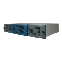
FR6822+ Frames
Installation and Operation Manual
25
Copyright © 2008-2011, Harris Corporation
The Frame ID rocker switches on the back of each frame can be set to one of four
combinations. Choose a different combination (a unique identifier) for each frame on the
control network. (Push down for the “On” position.) See Table 2-5.
4 Connect one end of a straight-through RJ-45 Ethernet cable to the RJ-45 Ethernet port on
the back right of the FR6822+QXFE frame, and connect the other end to a PC or Ethernet
hub or switch.
See FR6822+QXFE Configuration, Monitoring, and Control on page 31 for information
on setting up and using the 6800+ETH.
When the serial connection is set up correctly, after you discover or browse to the
6800+ETH module, its host frame will appear as the parent frame, with the other three
frames appearing as child frames. You can view the serially connected frames and the
modules they contain in CCS Navigator, an HTTP web browser, or a third-party SNMP-based
control application (if you have the optional SNMP license installed on the 6800+ETH
module).
Connecting the GPI Alarm Relay to a Monitoring System
To send alarm signals from the FR6822+ frame to a control monitoring system, follow these
steps:
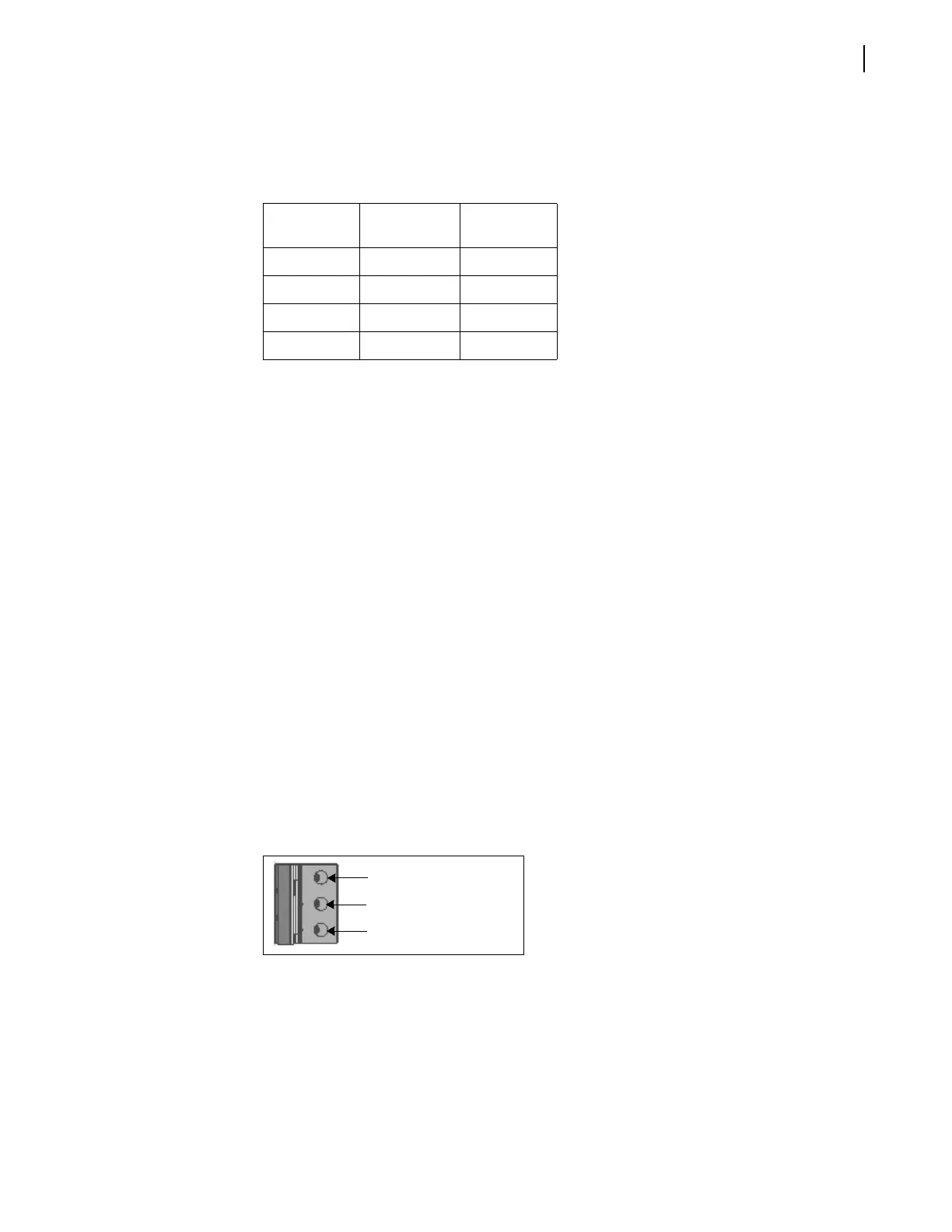
1 Connect 1 end of a 3-conductor, 18 to 25 gauge cable to the GPI connector at the back of
the frame.
2 Connect the other end of the cable to a customer supplied monitoring panel.
Figure 2-19 shows the GPI alarm relay connector (with a terminal block connector plug),
and describes the pinouts.
Figure 2-19 GPI Alarm Connector
See Monitoring the Frame Using Frame Status LEDs on page 27 for more information
on FR6822+ alarms.
Table 2-5 Identifying Frames on the Control Network
Frame
Frame ID
Switch 0
Frame ID
Switch 1
1OffOff
2OnOff
3OffOn
4OnOn
NO (Normally open)
COM (Common)
NC (Normally closed)