Chapter 2
Installation
24
Copyright © 2008-2011, Harris Corporation
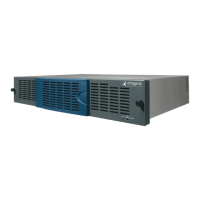
Figure 2-16 Typical System Configuration
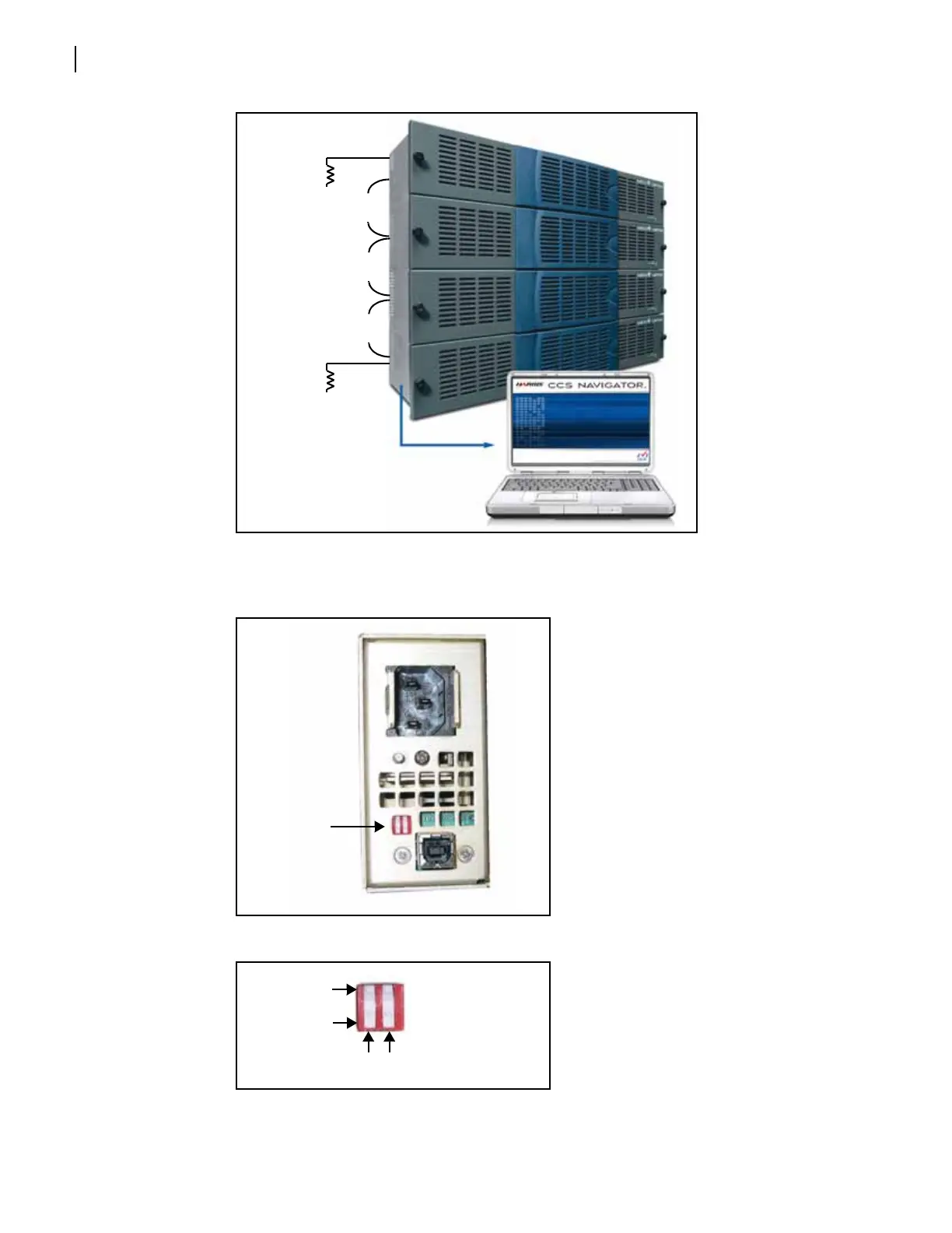
3 Identify each frame on the network by setting a unique switch combination for every frame.
Figure 2-17 Left Rear of FR6822+ Frame
Figure 2-18 Frame ID Rocker Switches
Termination
point - 75
6800+ control network
BNC coax connection
6800+ control network
BNC coax connection
6800+ control network
BNC coax connection
Termination point - 75
Ethernet connection to CCS,
SNMP network, or internet