FR6822+ Frames
Installation and Operation Manual
21
Copyright © 2008-2011, Harris Corporation
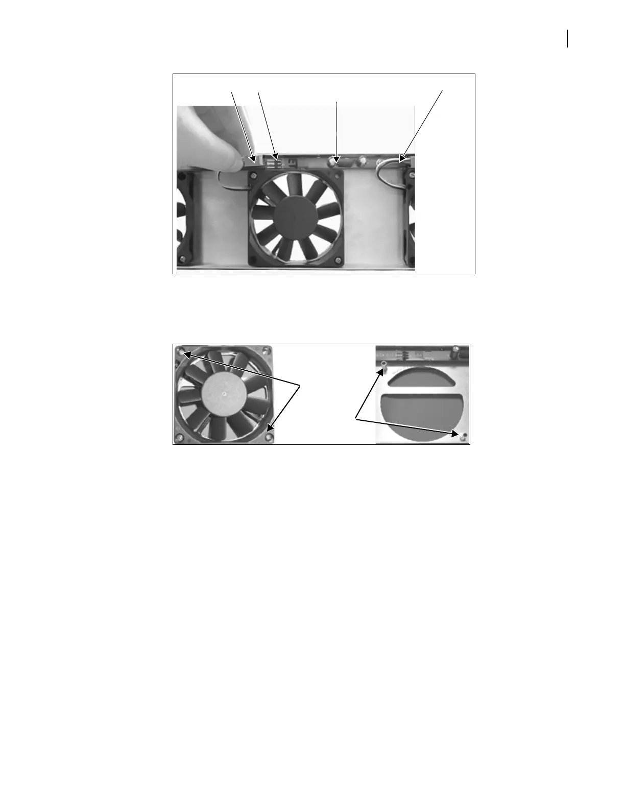
Figure 2-12 Removing Header Wires from Fan Assembly PCB Board
6 Unscrew the fan, and then pull it firmly away from the assembly to remove it from the
standoffs (see Figure 2-13).
Figure 2-13 Removing a Fan from the Assembly
7 Position a new fan over the assembly standoffs, and then fasten the fan into place with the
supplied screws (see Figure 2-11 on page 20).
(Ensure that the fan labelling is face down, and that the header wiring is at the top left
corner of the installed fan, as shown in Figure 2-12 on page 21.)
8 Connect each new fan’s header wires to the assembly PCB board (see Figure 2-12 on
page 21).
9 Replace the fan assembly inside the front cover, and then secure the assembly into place
with the provided screws.
Ensure that the following items are aligned:
The LEDs on the fan assembly PCB with the corresponding holes on the front panel
The fan assembly screw holes with the holes on the front panel
10 Close the front panel, and then reapply power to the frame.
Header wires
Connector
PCB board
(along top of fan assembly)
Header wires
A. Remove
screws
B. Pull fan off
its two
standoffs