Chapter 2
Installation
18
Copyright © 2008-2011, Harris Corporation
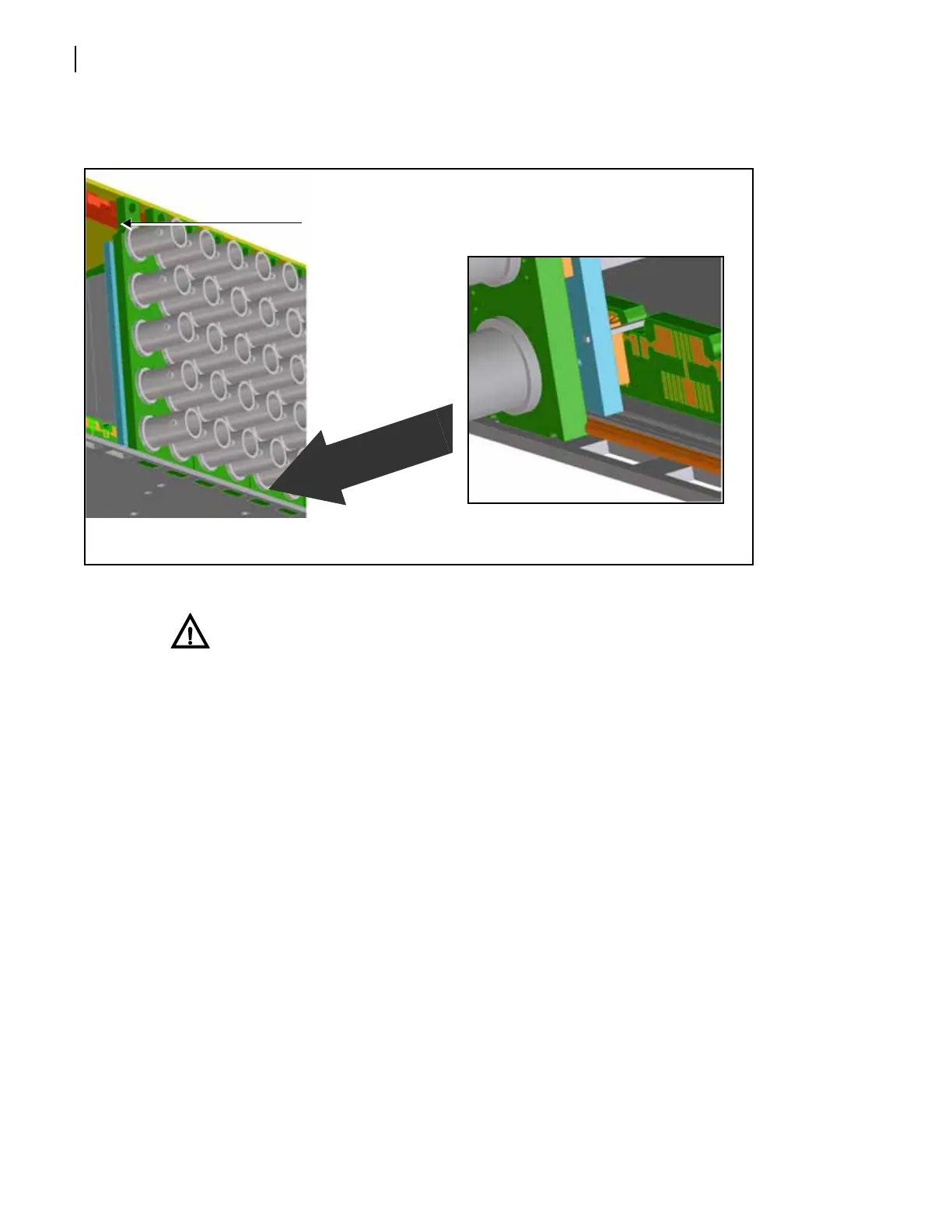
Ensure that the EMI gaskets on the right side of the back connector remain in place during
the installation. (The gaskets fit tightly.)
Figure 2-8 Installation of Back Connectors, Rear View
CAUTION
The front module must match the corresponding back connector; otherwise, the
modules will not operate correctly. Some module insertions may be prevented if
the modules are incompatible.
3 Apply the back connector labels to the back connecting module if these are supplied
separately.
4 Pull out the finger-release screws on the right and left side of the front panel, and then
open it.
5 Locate the front module slot that corresponds with the matching back connector.
6 Slide the module into the guides on the frame floor. See Figure 2-9 on page 19.
The module is properly seated when its edge is flush with the guide edge and the extractor
handle closes. See Figure 2-10 on page 19.
Insert the bottom lip of the back connector into the
slot on the bottom-edge of the frame.
After inserting the bottom lip of
the back connector into the
required slot (see the graphic
“Close-up, bottom” below), screw
the top of the back connector
Back of frame
Close-up, bottom