COMPUSHIFT II Manual – COMPUSHIFT II Manual
Specifications & Pinouts– 165
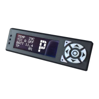
CONNECTOR ROW PIN TERMINATION WIRE COLOR FUNCTION NOTES
TRANS 2 A 3 FLYING LEAD Yellow / Red Engine Torque
Modulation
TRANS 2 A 4 MAIN-06 Blue / White Solenoid SR
TRANS 2 A 5 MAIN-14 Purple Solenoid S4
TRANS 2 A 6 MAIN-07 Light Blue Solenoid S3
TRANS 2 B 8 MAIN-03 Black Solenoid Ground for
SL1
or TRANS 1 B1
TRANS 2 B 8 MAIN-04 Black Solenoid Ground for
SLU
or TRANS 1 B1
TRANS 2 B 8 AUX-04 Black Solenoid Ground for
SL2
or TRANS 1 B1
TRANS 2 B 8 MAIN-05 Black Solenoid Ground for
SLT
or TRANS 1 B1
Note that ground wires MAIN-03, MAIN-04, AUX-04, and MAIN-05 can be connected to TRANS 1 B1 instead of TRANS 2
B8, depending on wiring loom build variation.
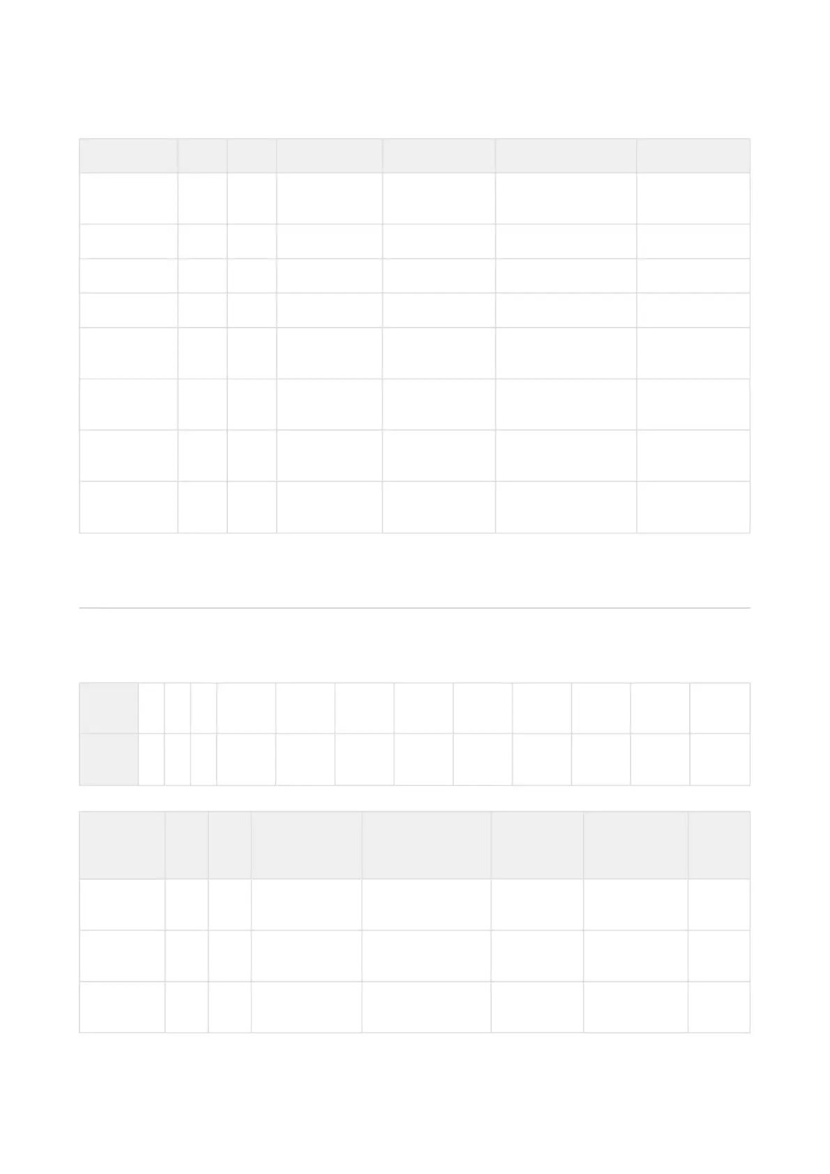
ENGINE Connector
A 1
2
1
1
1
0
9 8 7 6 5 4 3 2 1
B 1
2
1
1
1
0
9 8 7 6 5 4 3 2 1
Note: This is the view into the receptacle on controller, not the plug.
CONNECT
OR
RO
W
PIN PIN NAME FUNCTION WIRE
COLOR
TERMINATION NOTE
S
ENGINE A 1 TACH SIG IN INPUT RPM SIG BRN FLYING LEAD
ENGINE A 2
ENGINE A 3
 Loading...