97
8.3 Connections and Protocol Selection
8.3.1 Attaching the Connector
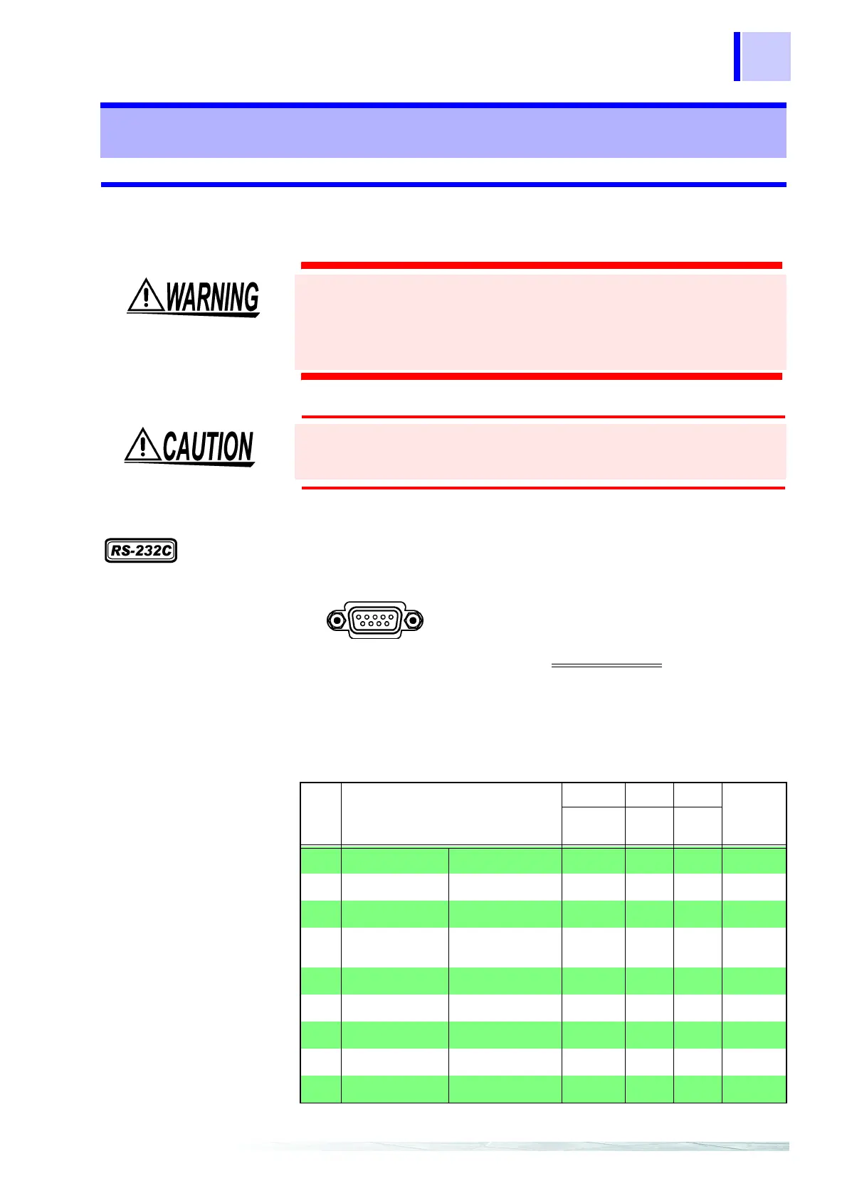
RS-232C Connector
8.3 Connections and Protocol Selection
• Always turn both devices OFF when connecting and
disconnecting an interface connector. Otherwise, an electric
shock accident may occur.
• To avoid damage to the product, do not short-circuit the
terminal and do not input voltage to the terminal.
After connecting, always tighten the connector screws. If the
connector is not secured, operation may fail to meet specifications,
and damage could result.
Male 9-pin D-sub
#4-40 attaching screws
Connect the RS-232C cable.
To connect the instrument to a controller
(DTE), use a crossover cable
compatible with
the connectors on both the instrument and the
controller.
The I/O connector is a DTE (Data Terminal Equipment) configuration.
This instrument uses only pins 2, 3 and 5. The other pins are
unconnected.
6 7 8 9
1 2 3 4 5
Pin
No.
Mutual connection circuit name
CCITT EIA JIS
Signal
Name
Circuit No.
Code
Addr.
Code
Addr.
1
unused
2
Receive Data Receive Data 104 BB RD RxD
3
Transmit Data Send Data 103 BA SD TxD
4
Data Terminal
Ready
Data Terminal
Ready
108/2 CD ER DTR
5
Signal Ground Signal Ground 102 AB SG GND
6
unused
7
Request to Send Request to Send 105 CA RS RTS
8
Clear to Send Clear to Send 106 CB CS CTS
9
unused