51
5.2 BIN Measurement Function
Function
Description
BIN Measurement compares a measured value with up to ten sets of
upper and lower thresholds (BIN0 to BIN9) in one operation, and
display the results.
Decision results are output at the EXT I/O connector.
❖ For details about BIN signal outputs at the EXT I/O connector, refer to 6.2
Signal Descriptions (Page 78).
To perform BIN measurement, first select the range, then set the
upper and lower thresholds or the reference value/tolerance for each
BIN No..
5.2 BIN Measurement Function
Setting upper and lower thresholds to judge measured values (BIN
Measurement Function)
Example: In the 2 kΩ range, set up two decision states using different upper/lower
thresholds (BIN0: Upper threshold 1 kΩ/Lower threshold 800 Ω and BIN2: Upper
threshold 900 Ω/ Lower threshold 700 Ω), and judge measurements.
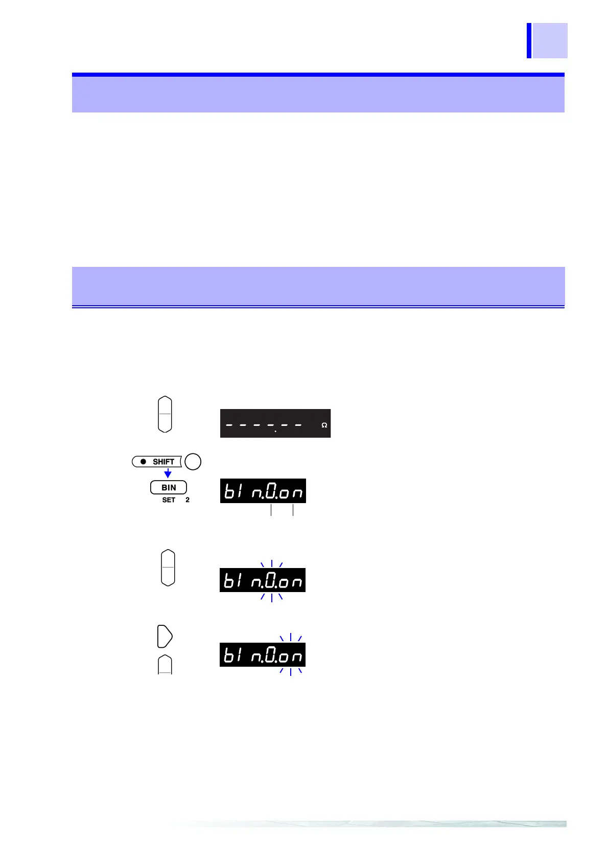
1
(BIN off)
Confirm that the BIN Measurement function is OFF.
2
Select the appropriate range.
3
(SHIFT Lamp lit)
The Bin No. setting display appears. (BIN lit)
4
Select the BIN No. (BIN No. = 0 to 9)
5
Select whether this BIN No. is to be enabled or disabled.
- -
.......... BIN measurement for this BIN No. is disabled.
on ......... BIN measurement for this BIN No. is enabled.
(Main Display)
In this case, set to 2 kΩ.
(2000.00 Ω)
(Main Display)
BIN No. BIN No. enabled/disabled
First set the conditions for BIN0,
then set the conditions for BIN2.
(Main Display)
In this case, select 0.
(Main Display)
In this case, select on.