19
2.3 Connecting the Test Leads
This instrument is equipped with an input with four separate banana-
jack terminals (INPUT A) and another input with a multipolar socket
(INPUT B).
The supplied Model 9287 CLIP TYPE LEAD and Hioki's various
optional measurement leads connect to the INPUT A terminals.
❖ Appendix 6 Test Lead Options (page 176)
For high-resistance and low-power measurements, the high noise
immunity of INPUT B offers advantages for high speed
measurements.
❖ 2.9 Selecting the Measurement Terminals (page 26)
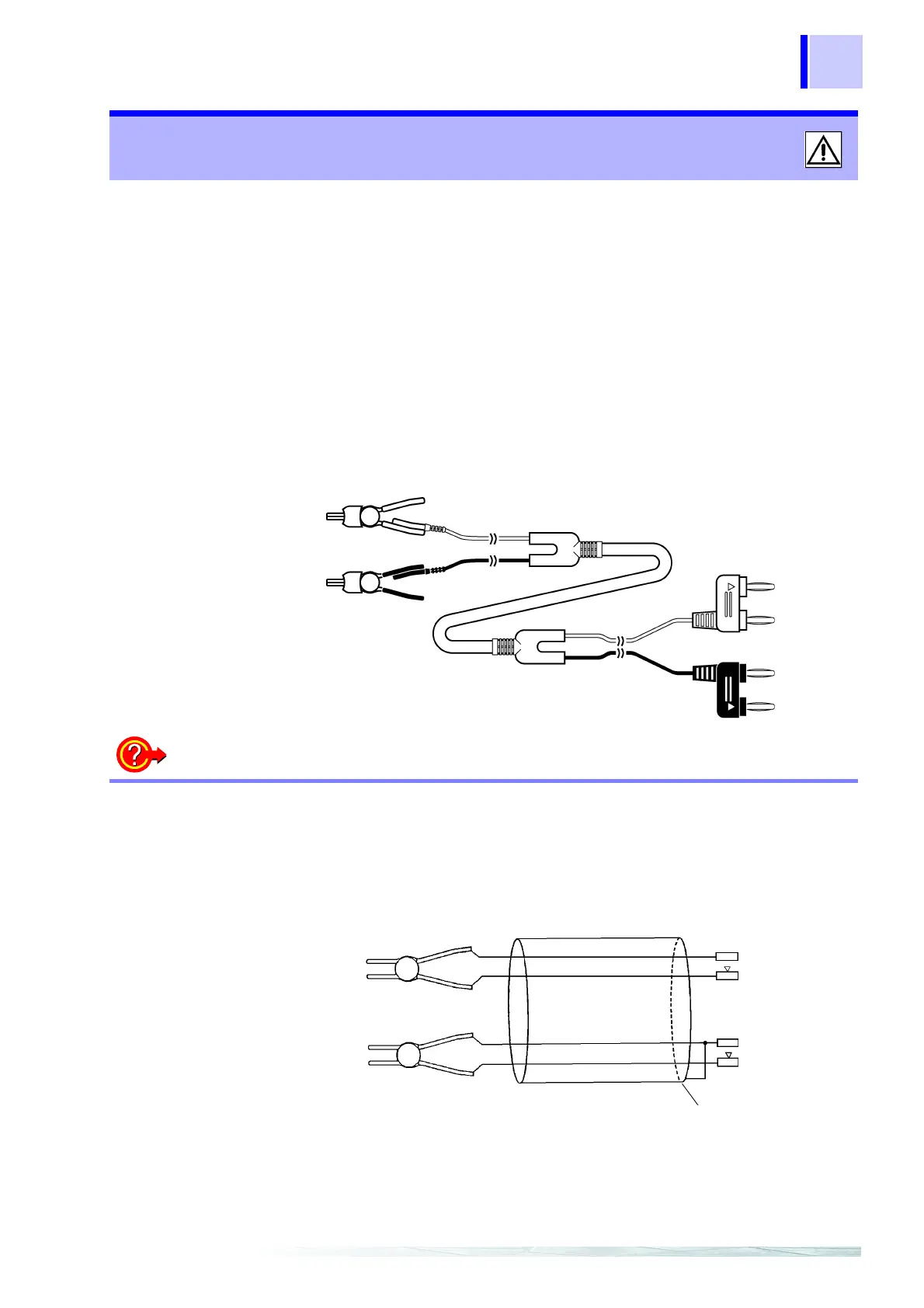
About Test Leads ______________________________________________
(Example: Model 9287 CLIP TYPE LEAD)
2.3 Connecting the Test Leads
SOURCE
SOURCE
SENSE
SENSE
Red
Black
Red
Black
SENSE
SENSE
SOURCE
SOURCE
Rubber Replacement
The 9287 CLIP TYPE LEAD is available as a service part (Rubber for
9099). Please contact your supplier or Hioki representative.
When replacing the rubber, lubricate the inside by moistening with
water before inserting the clip.
Making your own cable
The cable of our test leads is shielded.
When making your own cable, please bear in mind the following.
Connect the shield to the SOURCE-L lead.
Cable length must not exceed 5 m. (Conductor resistance should be
no more than 100 mΩ/m)
However, for the 20 mΩ and 200 mΩ ranges, resistance should be no
more than 300 mΩ per circuit.
SOURCE
SENSE
SOURCE
SENSE
SOURCE
SENSE
Red
Black
SOURCE
SENSE
Shield