29
3.1 Resistance Measurement
display app ears.
Before starting measurement, please read Safety Information (Page 2)
and Chapter 2 Measurement Preparations (Page 17).
The following example describes the resistance measurement process.
Example: Measuring a 10 mΩ shunt resistance
Measurement Chapter 3
3.1 Resistance Measurement
Required
items:
10 mΩ shunt resistance
9287 CLIP TYPE LEAD
Measurement
conditions:
Sampling ........................................ SLOW2
Zero adjust..................................... Enabled
Offset Voltage Compensation ........ Enabled
Range ............................................ 20 mΩ
Preparations
1 Connect the 9287 CLIP TYPE LEAD to the instrument, and turn it on.
❖ 2.3 Connecting the Test Leads (Page 19)
2 Select the appropriate line frequency and measurement terminals.
❖
2.8 Selecting the Line Frequency (Page 25)
❖ 2.9 Selecting the Measurement Terminals (Page 26)
Instrument Settings
Before setting, confirm that the SHIFT lamp is not lit.
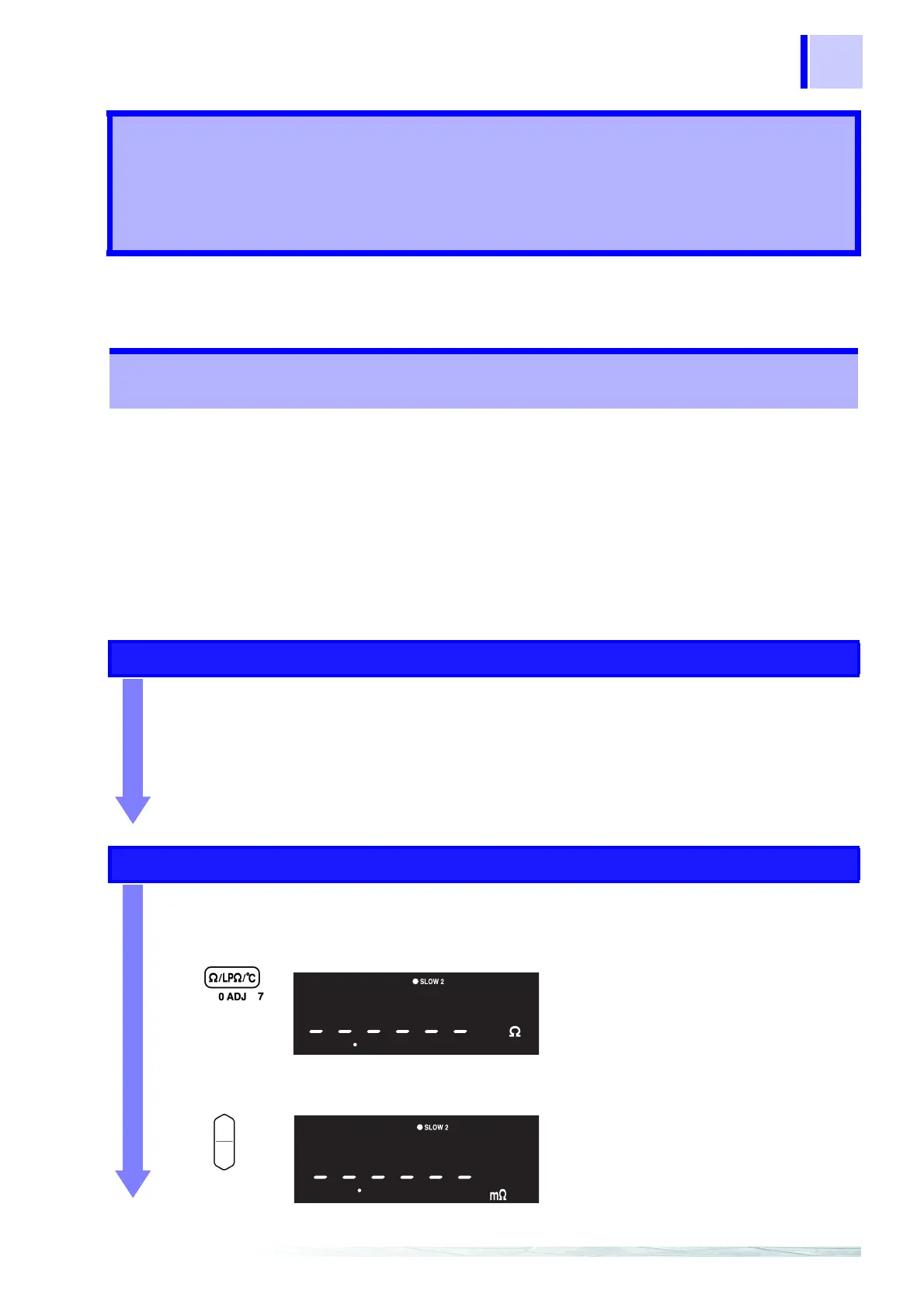
1 Select the Resistance Measurement function.
❖ 4.1 Selecting Measurement Functions (Page 37)
2 Set the measurement range to 20 mΩ.
❖
4.2 Measurement Range Setting (Page 38)
The Resistance Measurement display
appears.
(
Ω unit indicator lit, LP off)
(Main Display)
The position of the decimal and the unit
indicator change with each key-press.
(m
Ω lit, AUTO off)
(Main Display)