3.1 Resistance Measurement
30
Applying Temperature Correction
❖ 3.2 Temperature Measurement (Temperature Correction & Conversion) (Page 31),
5.4 Temperature Correction Function (TC) (Page 58)
Applying Temperature Conversion
❖
3.2 Temperature Measurement (Temperature Correction & Conversion) (Page 31),
5.5 Temperature Conversion Function (∆t) (Page 60)
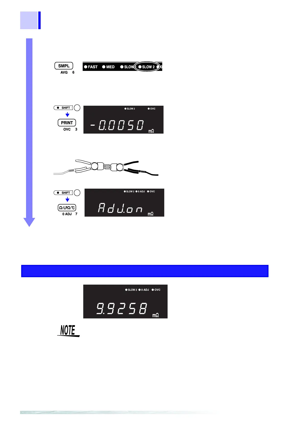
3 Set the sampling rate to SLOW2.
❖ 4.4 Sampling Rate Setting (Page 42)
4 Enable Offset Voltage Compensation.
❖ 5.7 Offset Voltage Compensation (OVC) (Page 65)
5 Execute zero-adjust.
❖ 4.3 Zero-Adjust Function (Page 40)
The lit position moves with each key-press.
(
SLOW2 lit)
(Main Display)
(OVC lit)
(Main Display)
SOURCE
SOURCE
SENSE
SENSE
Red
Black
Short together
the 9287 CLIP TYPE LEAD.
Accept the currently displayed value as the
zero-adjust value.
(
0ADJ lit)
(Main Display)
Measurement
Connect the 9287 CLIP TYPE LEAD to the shunt resistance, and read the value.
• In the 20 mΩ and 200 mΩ ranges, the sample can consume one
watt or more. Also, in the 100 kΩ range and above, up to 10 volts
may be applied. Therefore, when measuring delicate components,
use the Low-Power Resistance Measurement mode.
• In the following cases, the measured value may be displayed with
a "-" sign.
• If SOURCE and SENSE leads are reversed.
• If zero-adjust is performed by two-terminal measurement, and
contact resistance later decreases.
• If the thermoelectromotive force changes, or the offset voltage of
the instrument changes.