31
3.2 Temperature Measurement (Temperature Correction & Conversion)
Temperature
Correction
Using the temperature at time of measurement, temperature
correction is applied to convert the measured resistance value to the
value it would have at a specified reference temperature.
❖ 5.4 Temperature Correction Function (TC) (Page 58)
Temperature
Conversion
Temperature increase is derived by the temperature conversion
principle.
❖ 5.5 Temperature Conversion Function (∆t) (Page 60)
❖ Appendix 3 Temperature Conversion Function (∆t) (Page 172)
Temperature Measurement with the 9451 TEMPERATURE PROBE ______
3.2 Temperature Measurement
(Temperature Correction & Conversion)
Preparations
1 Connect the test leads and the 9451 TEMPERATURE PROBE to the
instrument, and turn it on.
❖ 2.3 Connecting the Test Leads (Page 19),
2.4 Connecting the Temperature Probe (Page 21)
2 Select the appropriate line frequency and measurement terminals.
❖ 2.8 Selecting the Line Frequency (Page 25),
2.9 Selecting the Measurement Terminals (Page 26)
Instrument Settings
Before setting, confirm that the SHIFT lamp is not lit.
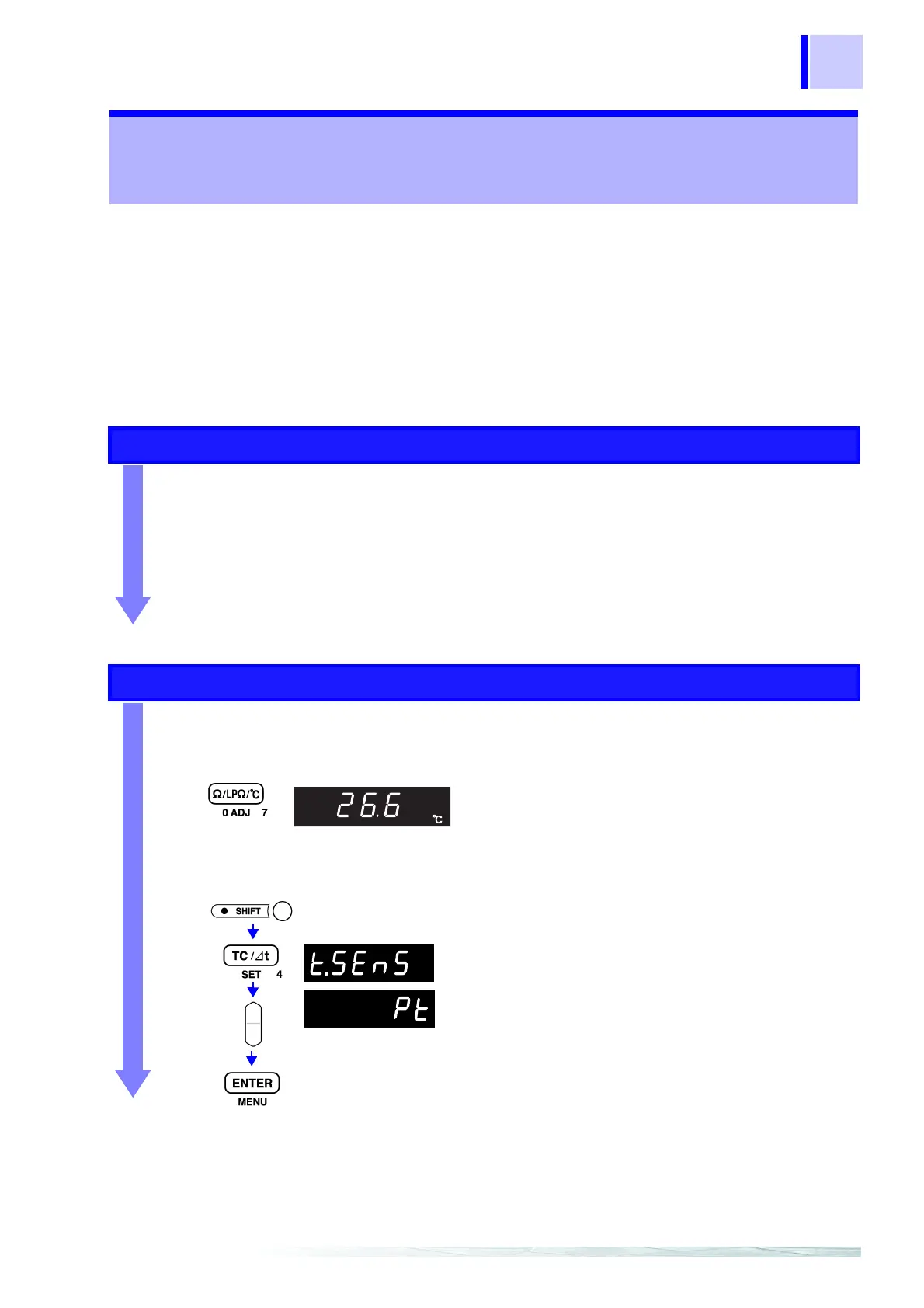
1 Select the Temperature Measurement function.
❖ 4.1 Selecting Measurement Functions (Page 37)
2 Select Pt for the temperature sensor type.
The Temperature Measurement display
appears.
(
°C unit indicator lit)
The current temperature appears.
(Main Display)
The temperature sensor type selection
display appears.
Select Pt.
Apply settings and return to the Measurement display.
(Main Display)
(Sub Display)